
Method of operating a wind turbine plant

a technology of wind turbines and wind power generators, applied in the direction of reactive power adjustment/elimination/compensation, parametric calibration/setting, ac network voltage adjustment, etc., can solve the problems of general inadequate infrastructure setup, fault current contribution could exceed the breaking capacity of circuit breakers, and the effect of exacerbated problems

Active Publication Date: 2017-01-31
VESTAS WIND SYST AS
View PDF13 Cites 12 Cited by
  • Summary
  • Abstract
  • Description
  • Claims
  • Application Information

AI Technical Summary

Benefits of technology

The invention provides many advantages over previous solutions and the prior art. However, not all advantages may be present in each embodiment. The patent text explains that the "technical effects" are only meant to be illustrative and cannot be considered elements or limitations of the appended claims, except where explicitly recited in a claim. The reference to "the invention" should not be construed as a generalization of any inventive subject matter disclosed herein and should not be considered to be an element or limitation of the appended claims, except where explicitly recited in a claim.

Problems solved by technology

As wind power plants are generally situated in rural areas, infrastructure is generally inadequately set up to support the wind power plant electrical distribution.
However, the present assignees of the application have discovered that during conditions when the grid short circuit strength increases, the fault current contribution could exceed the breaking capacity of the circuit breaker.
This issue is exacerbated in situations when additional power production units, for example more wind turbines, or gas turbines or coal plants, are added onto the transmission circuit of a wind power plant, and in situations of a fault, append their fault contribution onto the transmission circuit of the wind power plant.
This leads to further stress on the circuit breaker, which may permanently damage when undertaking a disconnection by opening a circuit which has been loaded with current that exceeds its rating.

Method used


Image

  • Method of operating a wind turbine plant
  • Method of operating a wind turbine plant
  • Method of operating a wind turbine plant

Examples


Embodiment Construction

[0014]In the following, reference is made to embodiments of the invention. However, it should be understood that the invention is not limited to specific described embodiments. Instead, any combination of the following features and elements, whether related to different embodiments or not, is contemplated to implement and practice the invention.

[0015]Furthermore, in various embodiments, the invention provides numerous advantages over the prior art. However, although embodiments of the invention may achieve advantages over other possible solutions and / or over the prior art, whether or not a particular advantage is achieved by a given embodiment is not limiting of the invention. Thus, the following aspects, features, embodiments and advantages are merely illustrative and are not considered elements or limitations of the appended claims except where explicitly recited in a claim(s). Likewise, reference to “the invention” shall not be construed as a generalization of any inventive subje...


PUM


Abstract

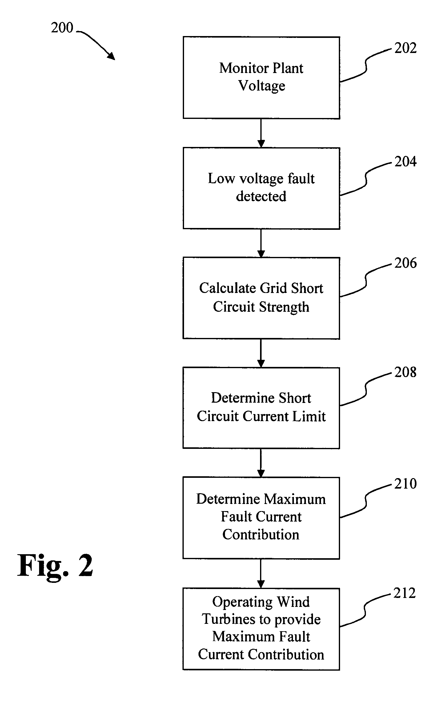
A method of operating a wind turbine plant is provided. Such a wind turbine plant comprises at least one transmission branch comprising a plurality of wind turbine generators and coupled to an electrical grid at a point of common coupling through at least one circuit breaker comprising a breaking capacity. The method comprises monitoring the electrical grid for a low voltage fault event; and if a low voltage fault event is detected: calculating a grid short circuit strength, determining a short circuit current limit if the grid short circuit strength requires an initial fault current contribution which exceeds the breaking capacity of the circuit breaker to be passed through the circuit breaker, determining a maximum fault current contribution based on the short circuit current limit and operating the wind turbine generators to provide to the electrical grid the maximum fault current contribution.

Description

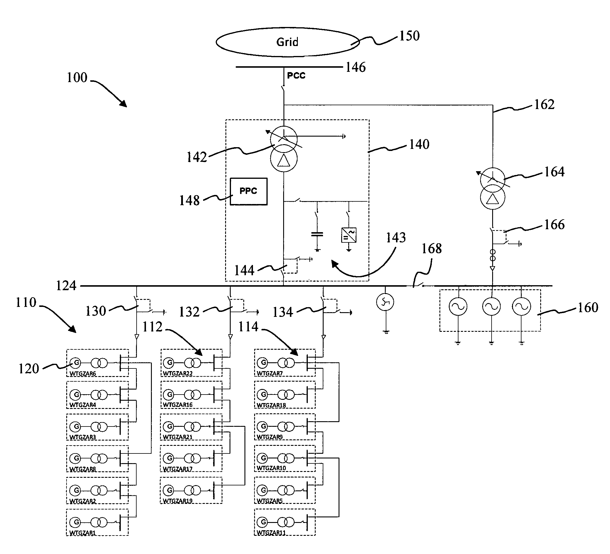
CROSS-REFERENCE TO RELATED APPLICATIONS[0001]This application is the national phase under 35 U.S.C. .sctn. 371 of PCT International Application No. PCT / DK2013 / 050039 which has an International filing date of Feb. 15, 2013, which designated the United States of America, the entire contents of which are hereby incorporated herein by reference.FIELD OF THE INVENTION[0002]The present invention generally relates to a method of operating a wind turbine plant, in particular operating a wind turbine plant during a low voltage fault situation, in particular a short circuit fault.BACKGROUND[0003]In recent years, there has been an increased focus on reducing emissions of greenhouse gases generated by burning fossil fuels. One solution for reducing greenhouse gas emissions is developing renewable sources of energy. Particularly, energy derived from the wind has proven to be an environmentally safe and reliable source of energy, which can reduce dependence on fossil fuels.[0004]Energy in wind ca...

Claims


Application Information

Patent Timeline
Patent Type & Authority Patents(United States)
IPC IPC(8): F03D9/00H02P9/00H02J3/18F03D7/02H02J3/16H01H81/00G05B23/02H01H71/10H02H3/08H02J3/38H02H3/02H02H3/00H02H7/093H02H7/30
CPCH02J3/381H02J3/382F03D9/005F03D7/0272G05B23/0235H01H71/10H01H81/00H02H3/006H02H3/025H02H3/08H02H7/093H02J3/16H02J3/18H02J3/38H02J3/386H02P9/006H02H7/30Y02E10/563Y02E10/763Y02E40/34F03D9/257H02J2300/28Y02E10/72Y02E10/76Y02E40/30H02J3/50F03D7/048
Inventor GUPTA, MANOJGURU, DILIP KUMARGUPTA, AMIT KUMAR
Owner VESTAS WIND SYST AS
Learn More