Control system for a plug-in hybrid vehicle

a technology of control system and hybrid vehicle, which is applied in the direction of engine-driven generators, machines/engines, vehicle sub-unit features, etc., can solve the problems of deterioration of power storage devices, and achieve the effect of shortening the time and suppressing the deterioration progress of capacitors

Inactive Publication Date: 2017-02-07
NISSAN MOTOR CO LTD
View PDF12 Cites 14 Cited by
  • Summary
  • Abstract
  • Description
  • Claims
  • Application Information

AI Technical Summary

Benefits of technology

[0007]The present invention was made in consideration of the above problem and aims to provide a control system for a plug-in hybrid vehicle that can achieve suppression of the deterioration progress of the capacitor when the ignition is on, while being able to shorten the time until a starter start-up permission at the time of reverse transition from the CS mode to the DC mode.
[0011]In other words, the engine start in the CD mode is performed basically by the starter start-up while the engine start in the CS mode is performed basically by an M / G start using the motor / generator. That is, during selection of CS mode, it is not necessary to elevate the capacitor voltage for preparation of the starter start-up. On the other hand, while the CD mode is being selected, it is necessary to prepare for the starter start-up. Thus, when the CD mode is selected, the capacitor voltage is maintained at or below the deterioration free voltage. Further, at the time of reverse transition from the CS mode to the CD mode, instead of being responsive to completion of the reverse transition to the CD mode, once the reverse transition prediction has been established, recharging to the starter start-up permission voltage or more will be carried out. Consequently, when the ignition is on, while suppressing the deterioration progress of the capacitor, it is possible to shorten the time required until the starter start-up permission at the time of reverse transition from the CS mode to the CD mode.

Problems solved by technology

Therefore, a problem arises that deterioration of the power storage device proceeds due to an increase in the internal resistance of power storage device.

Method used


Image

  • Control system for a plug-in hybrid vehicle
  • Control system for a plug-in hybrid vehicle
  • Control system for a plug-in hybrid vehicle

Examples


first embodiment

[0018]First, a description is given of the configuration. The configuration of the FF plug-in hybrid vehicle employing the control system of the first embodiment (an example of a plug-in hybrid vehicle) is described separately in a “Drive System Configuration”, “Power Supply System Configuration”, “Control System Configuration”, and “Detailed Configuration of Capacitor Charge and Discharge Control”.

Drive System Configuration

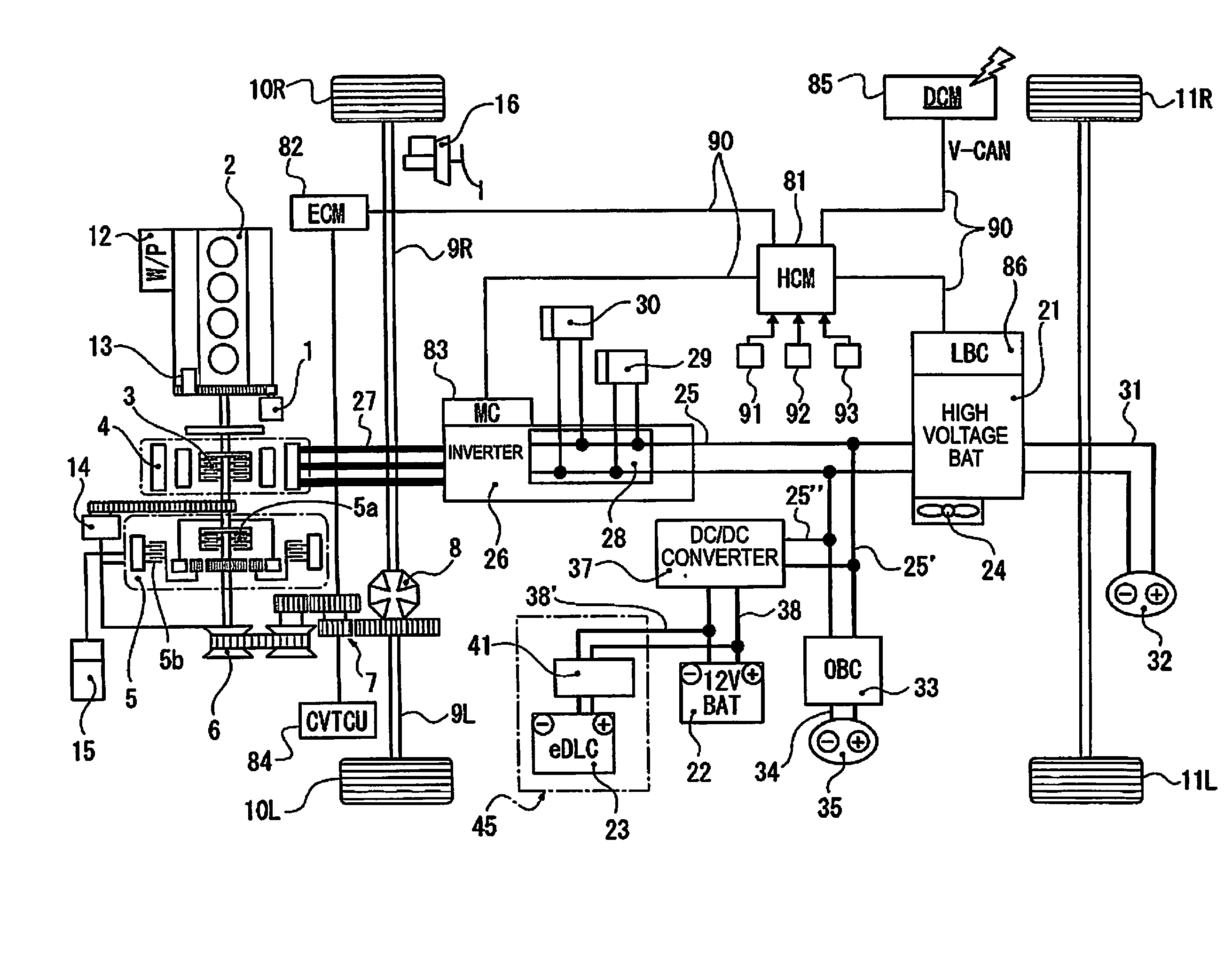
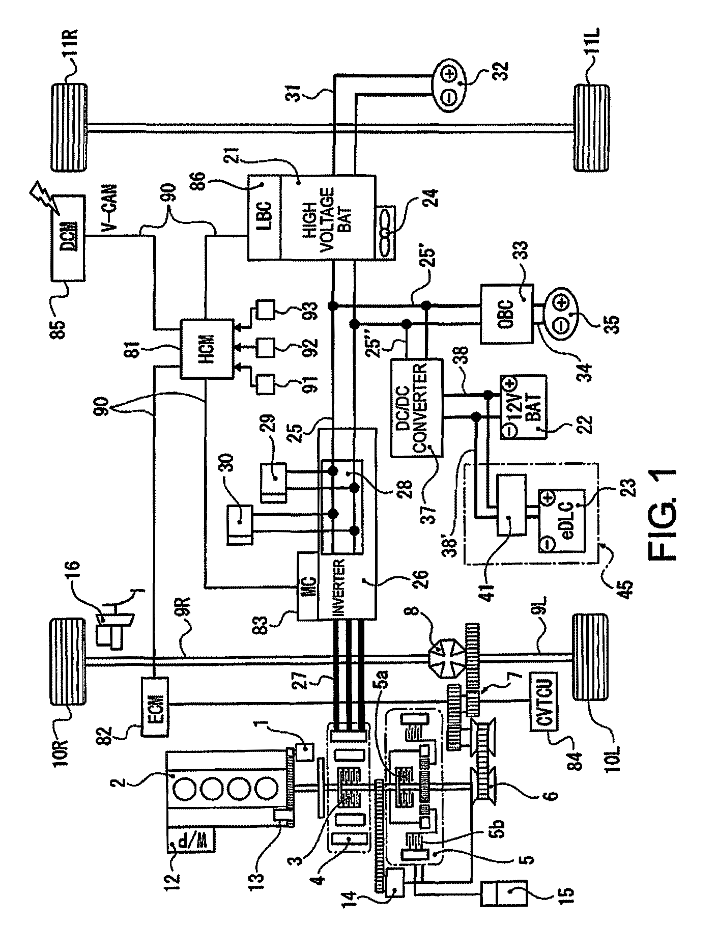
[0019]FIG. 1 is an overall system diagram showing an FF plug-in hybrid vehicle. Below, a description is given of a drive system configuration of the FF plug-in hybrid vehicle.

[0020]As shown in FIG. 1, as the drive system, a starter motor 1 (abbreviated as “M”), a transverse engine (abbreviated as “ICE”), a first clutch 3 (abbreviated as “CL1”), a motor / generator 4 (abbreviated as “M / G”), a second clutch 5 (abbreviated as “CL2”), and a belt-type continuously variable transmission (abbreviated as “CVT”) are provided. An output axis of the belt-type CVT 6 is driving...


PUM


Abstract

A control system for a plug-in hybrid vehicle includes a drive system including a starter motor, a transverse engine, and a motor / generator, and a power supply system including a high voltage battery, a capacitor, and a hybrid control module that controls charging and discharging of the capacitor. In the control system for an FF plug-in hybrid vehicle in which an external charging of the high-power battery is available, the hybrid control module starts the starter, performs mode selection control and charge / discharge control, maintains a capacitor voltage at or below a deterioration free voltage when the CS mode is selected during ignition on, and recharges the capacitor to a starter start-up permission voltage that allows the starter to start when a pre-forecast of the reverse transition from the CS mode to the CD mode is established.

Description

CROSS-REFERENCE TO RELATED APPLICATIONS[0001]This application is a U.S. National stage application of International Application No. PCT / JP2014 / 058470, filed Mar. 26, 2014, which claims priority based on Japanese Patent Application No. 2013-112749, filed in the Japan Patent Office on May 29, 2013, the contents of each of which is hereby incorporated herein by reference.BACKGROUND[0002]Field of the Invention[0003]The present invention relates to a control system for a plug-in hybrid vehicle with a starter motor having a capacitor as power supply in which charging of a high voltage or power battery is enabled by external charging.[0004]Background Information[0005]Conventionally, a power storage device is known in which the voltage of the power storage device is controlled between a preset lower limit voltage and a preset holding or sustaining voltage, when the vehicle is not in use. The storage device is configured to be fully charged when the vehicle recognizes the driver through a ve...

Claims


Application Information

Patent Timeline
Patent Type & Authority Patents(United States)
IPC IPC(8): B60K6/48F02N11/04B60L11/18B60L11/00B60L7/24B60L7/14B60L1/00F02D29/02B60W20/00B60W10/26B60L11/14B60K6/543B60R16/03B60W10/08B60W30/182B60W30/18B60W10/06F02N11/08F02N11/00F02N15/06F02N11/10F02N15/02B60L50/16
CPCB60W20/13B60K6/48B60K6/543B60L1/00B60L1/003B60L7/14B60L7/24B60L11/005B60L11/14B60L11/1816B60L11/1859B60L11/1862B60L11/1868B60W10/06B60W10/08B60W10/26B60W20/00B60W30/182B60W30/18009F02D29/02F02N11/04F02N11/084F02N11/0866Y02T10/7077Y02T10/7225Y02T10/7233Y02T10/84Y02T90/127Y02T90/14Y10S903/93B60L2210/12B60L2210/14B60L2240/34B60L2240/545B60L2240/547B60L2240/549B60L2260/26B60L2260/50B60W2710/06B60W2710/08B60W2710/244B60Y2400/114B60Y2400/214F02N11/006F02N11/087F02N11/101F02N15/02F02N15/067F02N2011/0885F02N2011/0888F02N2300/304Y02T10/48Y02T10/6221Y02T10/70Y02T10/7005Y02T10/7022Y02T10/7044Y02T10/7066Y02T10/7072B60L50/16B60L50/40B60L53/14B60L58/13B60L58/20Y02T10/40Y02T10/62Y02T10/72Y02T90/12
Inventor KODAWARA, TOMOYUKI
Owner NISSAN MOTOR CO LTD
Why Eureka
Try Eureka