Dosing system for a liquid reducing agent

a technology of reducing agent and dosing system, which is applied in the direction of positive displacement liquid engines, machines/engines, mechanical equipment, etc., can solve the problems of small demands placed on the delivery pressure of the aeration pump, small delivery rate, etc., and achieves simple and cost-effective effects, increase impermeability, and dissipate pressure spikes

Active Publication Date: 2017-02-07
ROBERT BOSCH GMBH
View PDF41 Cites 2 Cited by
  • Summary
  • Abstract
  • Description
  • Claims
  • Application Information

AI Technical Summary

Benefits of technology

[0006]The inventive dosing system is characterized in that said system is very cost effective and ensures a reliable evacuation or aeration of the dosing system after shutting down the internal combustion engine. Because the inventive aeration pump only serves to aerate or evacuate the dosing system, a very small delivery rate is sufficient. Moreover, only small demands are placed on the delivery pressure of the aeration pump. This leads to the aeration pump according to the invention being more cost effective than a 4 / 2-way valve. In addition, such a pump is less subject to malfunction than a switchable 4 / 2-way valve.

Problems solved by technology

Because the inventive aeration pump only serves to aerate or evacuate the dosing system, a very small delivery rate is sufficient.
Moreover, only small demands are placed on the delivery pressure of the aeration pump.

Method used


Image

  • Dosing system for a liquid reducing agent
  • Dosing system for a liquid reducing agent
  • Dosing system for a liquid reducing agent

Examples


Embodiment Construction

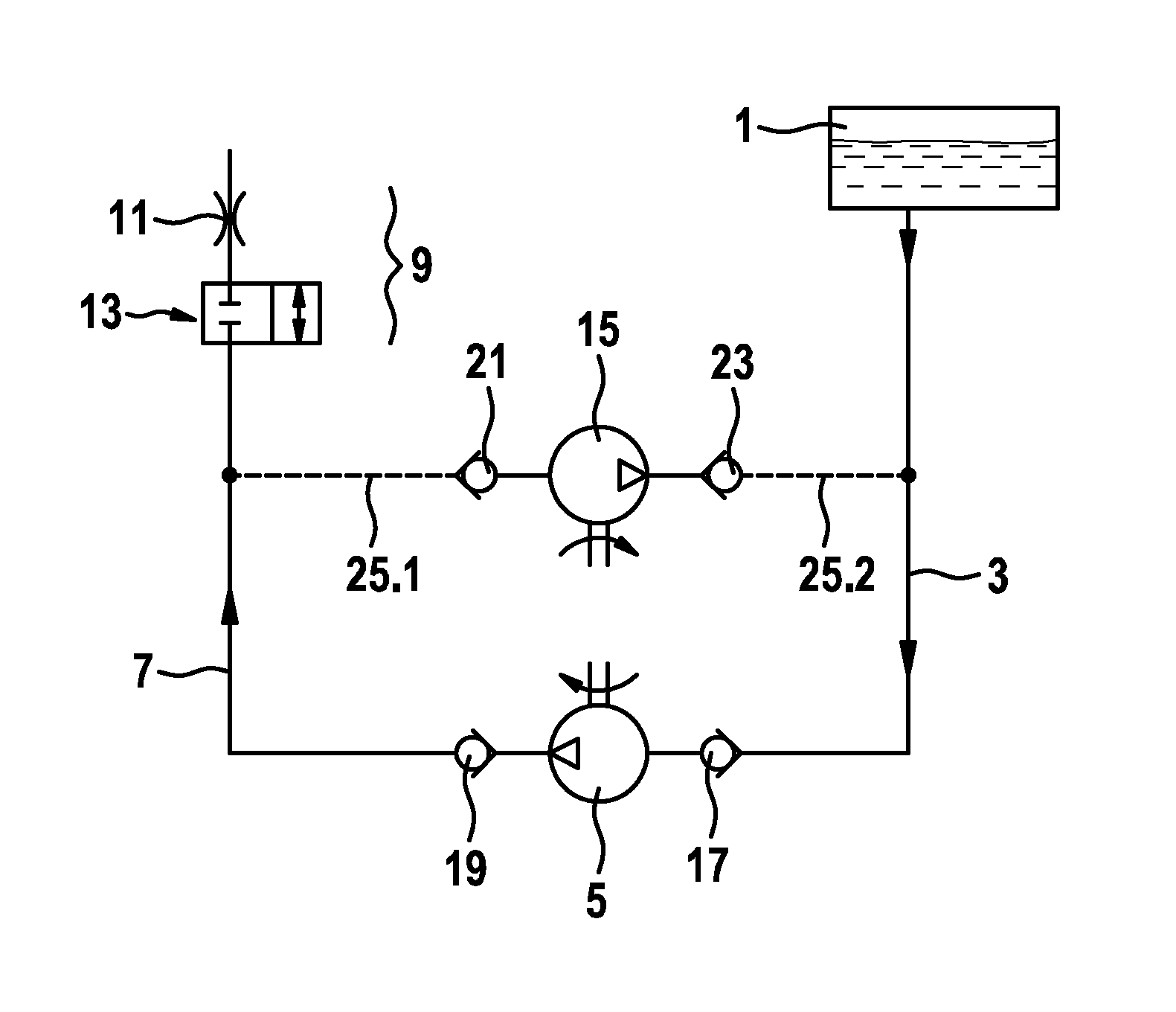
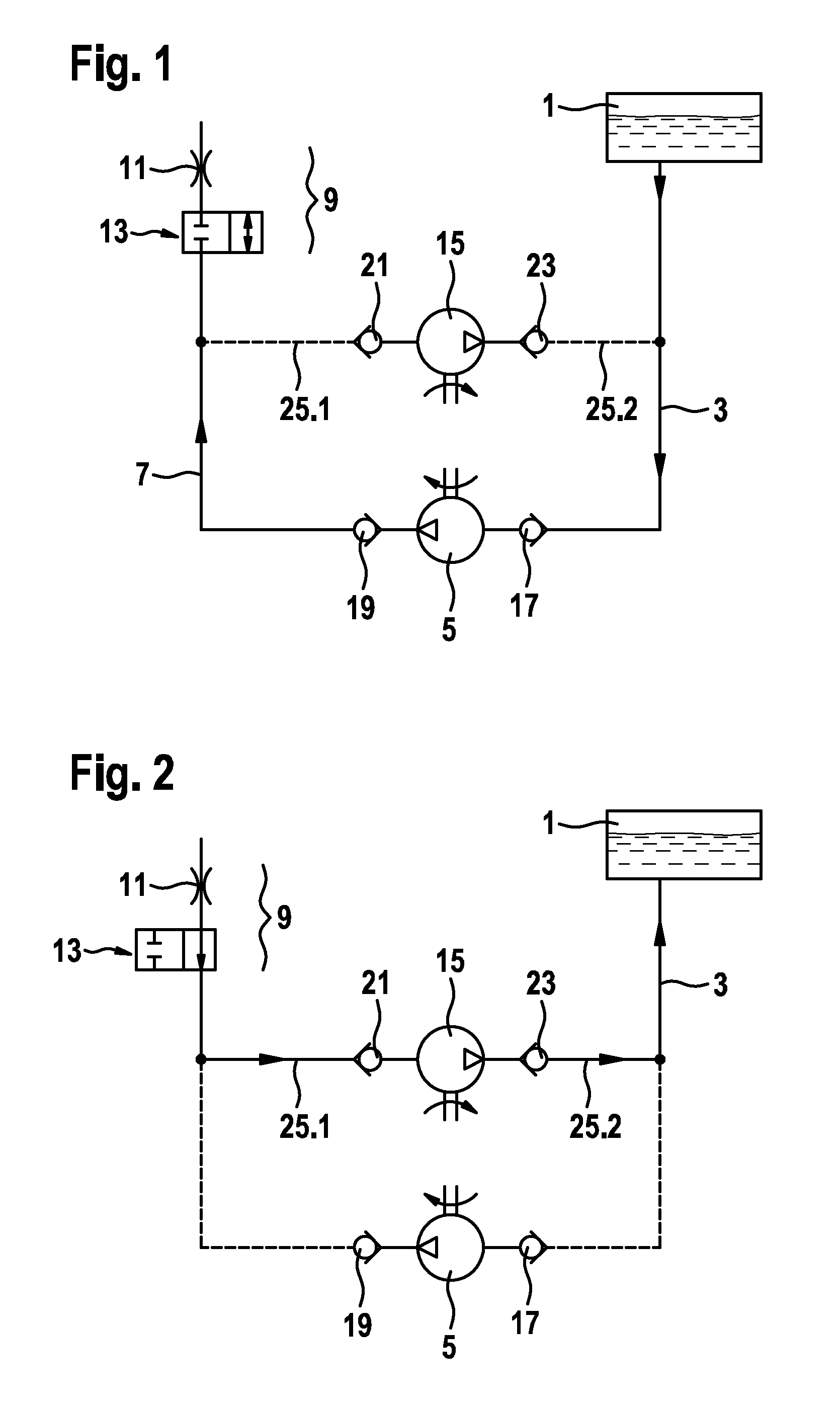
[0039]A first exemplary embodiment of a dosing system according to the invention is depicted as a block diagram in FIG. 1. Liquid reducing agent (urea-water solution) is situated in a tank 1. A delivery pump 5 draws liquid reducing agent as required out of the tank via a suction line 3 and delivers the same via a pressure line 7 to a dosing module 9. The terms suction line 3 and pressure delivery line 7 relate to the normal operation of the dosing system when reducing agent is namely being delivered from the tank to the dosing module 9.

[0040]The dosing module 9 is depicted in the block diagram as a combination of a throttle 11 and a switchable 2 / 2-way valve 13. The directional valve 13 is closed in the deenergized state. No liquid reducing agent is then injected into the exhaust tract of the internal combustion engine (not depicted). If reducing agent is being delivered by the delivery pump 5 and therefore the reducing agent is subjected to an increased pressure in the pressure line...


PUM


Abstract

Proposed is a dosing module for injecting liquid urea-water solution into the exhaust tract of an internal combustion engine, which dosing module is composed of two pumps, specifically a delivery pump (5) and an aeration pump (15). This permits firstly the injection of urea-water solutions and secondly safe and reliable ventilation of the system when the internal combustion engine is to be shut down.

Description

BACKGROUND OF THE INVENTION[0001]In internal combustion engines which operate according to the diesel process, an SCR catalyst is often provided in the exhaust gas system in order to meet environmental regulations. In order that the SCR catalyst can convert the NOx compounds contained in the exhaust gas to water and atmospheric nitrogen, a liquid urea-water solution (reducing agent) has to be injected into the exhaust tract upstream of the SCR catalyst. To this end, a dosing system comprising a tank, a pump and a dosing module, which operates similarly to the injector of a fuel injection system, is used. The pump is also referred to as the delivery module.[0002]It is the task of the delivery module or the pump to draw urea-water solution from a tank and to build up a sufficient pressure on the pressure side so that the liquid urea-water solution is finely atomized as soon as the dosing module opens in a demand-controlled manner. Just as the delivery module, the injector is connected...

Claims


Application Information

Patent Timeline
Patent Type & Authority Patents(United States)
IPC IPC(8): F01N3/10F01N3/20F01N3/24F04B23/10
CPCF01N3/10F01N3/208F01N3/2066F01N3/24F01N2610/02F01N2610/1433F01N2610/1466F01N2610/1473F01N2610/1493F04B23/10F04B23/12
Inventor LANDES, EWGENIJBOEHLAND, PETER
Owner ROBERT BOSCH GMBH
Why Eureka
Try Eureka