Method for controlling gear shift

a technology of power transmission and gear shift, which is applied in the direction of power to power outlet, agricultural machines, gearing, etc., can solve the problems of reducing the overall efficiency due to additional building components, the corresponding electronics, and reducing the power level of each individual machin

Active Publication Date: 2017-02-07
DEERE & CO
View PDF9 Cites 38 Cited by
  • Summary
  • Abstract
  • Description
  • Claims
  • Application Information

AI Technical Summary

Benefits of technology

[0011]In another embodiment, reactive power circulation in a variator branch against the original direction can be used to cover an external power requirement. For this purpose, a gear shift region of the transmission with variable gear shift can be specifically set such that the compound gear train delivers power to the variator branch. This power delivered to the variator branch is not fed back as reactive power into the compound gear train because, according to this embodiment, it is directed by the second electric machine and by the controller as electric power to cover the external power demand. If the external power requirement cannot be met by the second electric machine alone, the first electric machine can also be operated as a generator, so that both electric machines are operated within the meaning of cogeneration. By means of two electric machines, an external power demand can be covered so that the power level of each individual machine and the corresponding electronics can be reduced.

Problems solved by technology

This, however, incurs additional production costs and the overall efficiency is reduced due to additional building components.
This approach produces or consumes the electric power required for controlling the DC link.

Method used


Image

  • Method for controlling gear shift
  • Method for controlling gear shift
  • Method for controlling gear shift

Examples


Embodiment Construction

[0034]The embodiments of the present disclosure described below are not intended to be exhaustive or to limit the disclosure to the precise forms in the following detailed description. Rather, the embodiments are chosen and described so that others skilled in the art may appreciate and understand the principles and practices of the present disclosure.

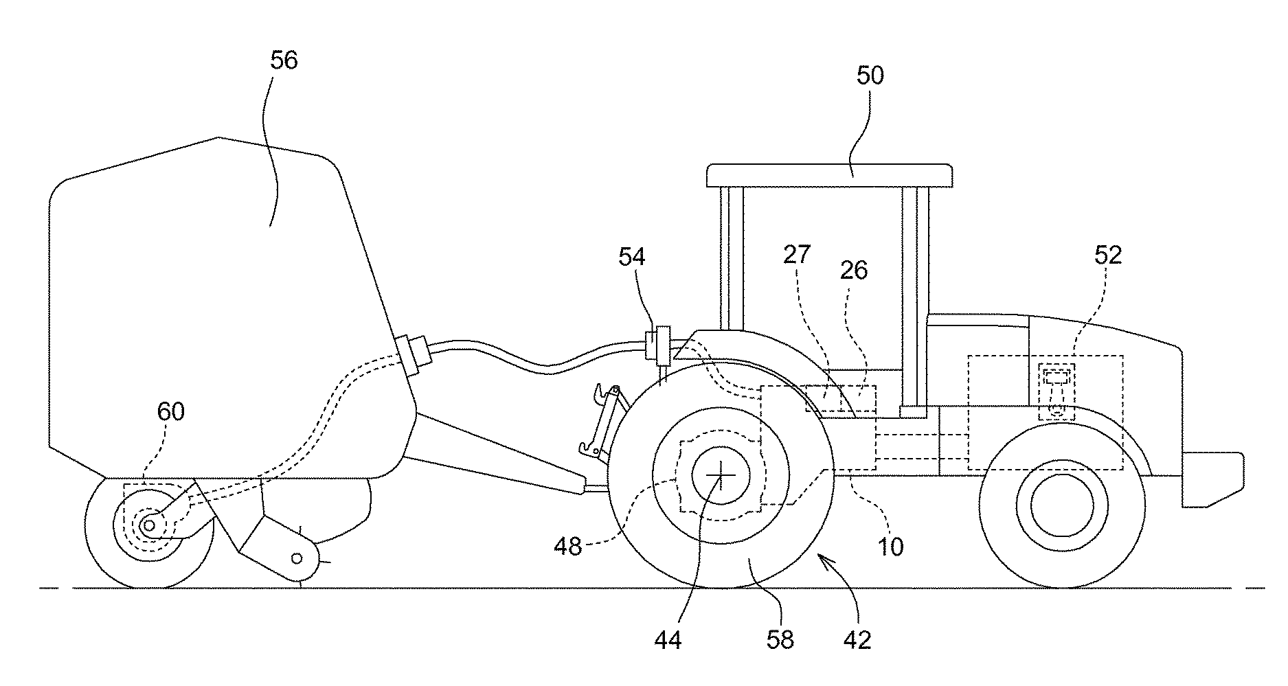
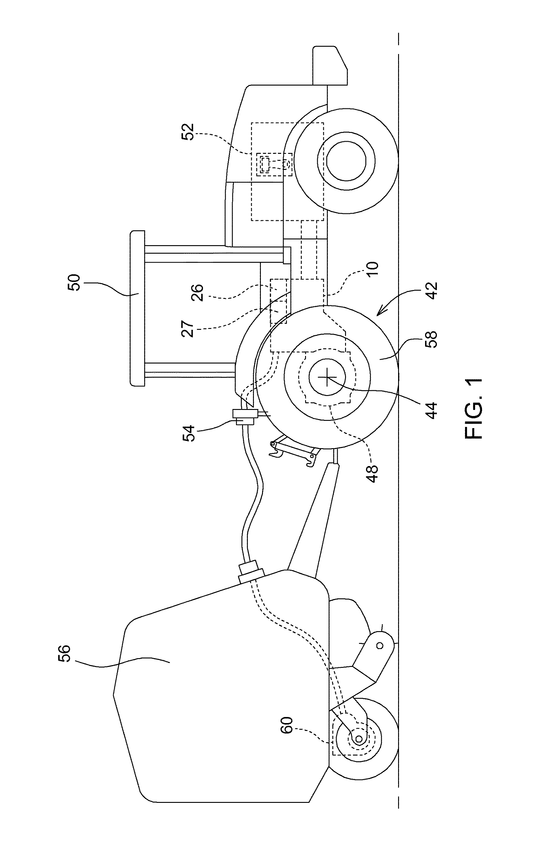
[0035]FIG. 1 shows an embodiment of an agricultural work vehicle 50 with a power-split transmission device 10, which is driven by a drive motor 52 and is constructed so as to provide electric power via a controller 26 and a power interface 54 in the form of an AEF connector to an electric consumer 60 in form of an electric drive axle on an implement 56. Further, drive power is transmitted to a drive system 42 via the transmission 10. The drive system 42 may have a differential transmission 48 and a drive axle 44 having wheels 58. In addition, an energy storage 27 connected to a controller 26 may be provided in order to store and dispens...


PUM


Abstract

A method for controlling a power-split gear shift device in a vehicle by providing an electric variator and a transmission with variable gear shift and connecting a drive motor to a traction drive of the vehicle. The electric variator has a compound gear train with at least one first and at least one second electric machine. The method also includes providing a controller for the electric machines for steplessly varying a gear shift of the compound gear train. Upon detection of an external power requirement by an electric consumer, a gear shift region of the transmission with variable gear shift is set to operate the first electric machine in a generator mode and to operate the second electric machine to compensate for an existing power deficit or a power excess relative to an external power demand.

Description

RELATED APPLICATIONS[0001]This application claims the benefit of German Application Ser. No. 102014219438.5, filed Sep. 25, 2014 and of German Application Ser. No. 102015208160.5, filed May 4, 2015, the disclosures of which are hereby expressly incorporated by reference in their entirety.FIELD OF THE DISCLOSURE[0002]The present disclosure relates to a method for controlling a power-split transmission, in particular in a vehicle, wherein the gear shift device comprises an electric variator and a transmission with variable gear shift to connect a drive motor with a drive system of the vehicle and wherein the electric variator comprises, a compound gear train, at least one first and at least one second electric machine, and a control of the electric machine for stepless variation of a gear shift of the compound gear train.BACKGROUND OF THE DISCLOSURE[0003]Stepless power-split transmission devices are particularly common in the premium segment of construction machinery and agricultural ...

Claims


Application Information

Patent Timeline
Patent Type & Authority Patents(United States)
IPC IPC(8): B60K1/02B60L1/00B60K6/445B60K6/365A01B61/00F16H61/04F16H61/686F16H61/66B60W10/26B60W10/105B60W30/188F16H3/72F16H37/08
CPCF16H3/728A01B61/00B60K6/365B60K6/445B60L1/006B60W10/105B60W10/26B60W30/188F16H61/04F16H61/66F16H61/686B60W2510/305B60W2530/16B60W2710/08B60W2710/1005F16H2037/0886F16H2061/6603F16H2200/2007F16H2200/2023F16H2200/2051B60L1/003B60L2200/40B60L2240/421B60L2240/423B60L2240/486B60L2240/507Y02T10/64B60W10/111B60W10/30B60W20/30B60W30/1886B60K6/547B60K6/387Y02T10/62
Inventor REKOW, ANDREW K.JEFFRIES, DENNIS L.FRITZ, NORBERTMUELLER, DAVIDGUGEL, RAINER
Owner DEERE & CO
Why Eureka
Try Eureka