
Spatially self-similar patterned illumination for depth imaging

a patterned illumination and self-similar technology, applied in image enhancement, image analysis, instruments, etc., can solve the problems of slowness, limited quantitative stereo vision usefulness, and inability to identify correspondences,

Active Publication Date: 2017-02-07
COGNEX CORP
View PDF38 Cites 19 Cited by
  • Summary
  • Abstract
  • Description
  • Claims
  • Application Information

AI Technical Summary

Benefits of technology

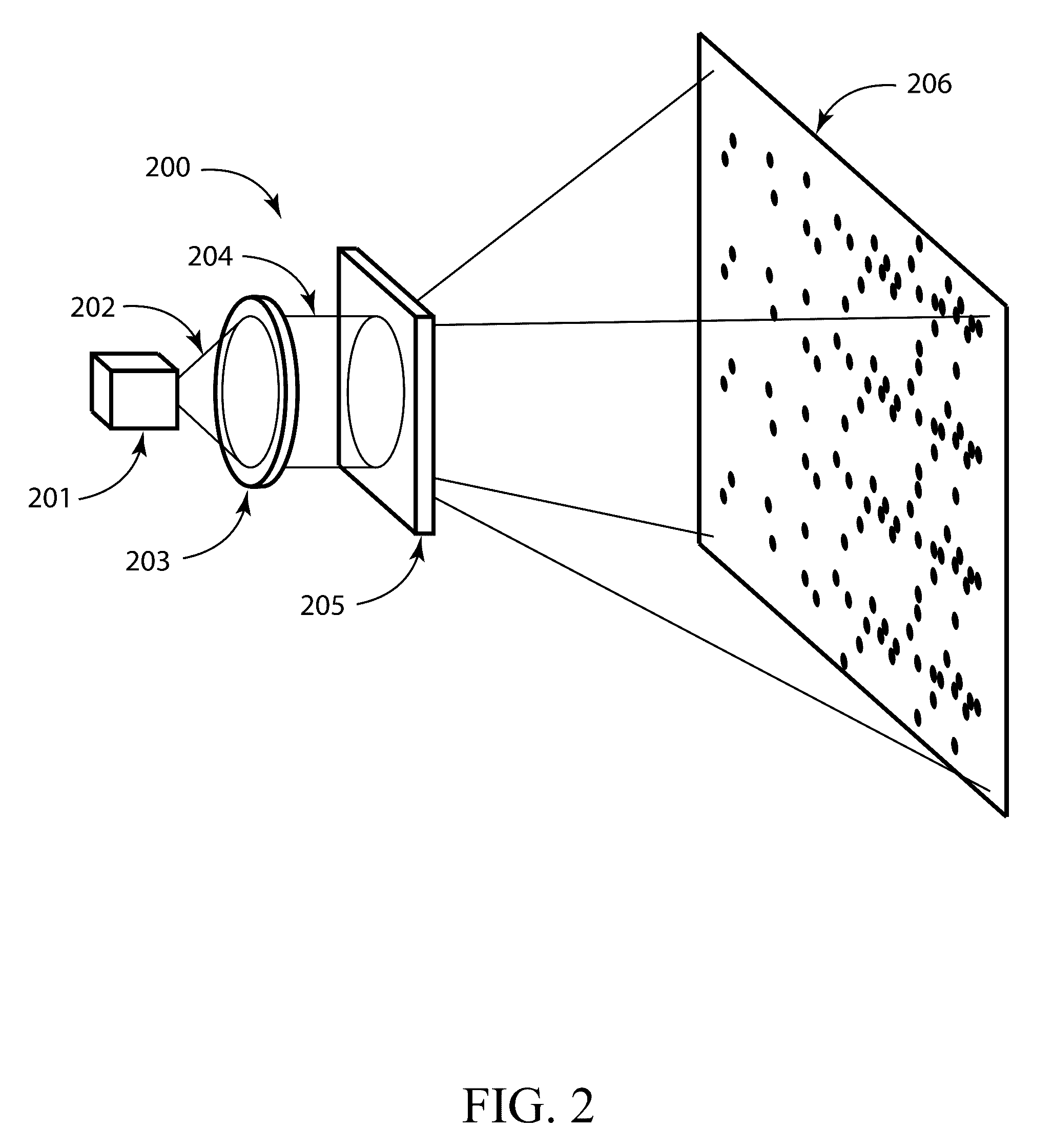
This patent describes methods, devices, and systems for using patterned radiation to estimate the coordinates of a location on an object in a 3D scene. The patterned radiation includes multiple spatial symbols that have different characteristics, such as amplitude or frequency, in their distribution. The multiple spatial symbols can be distinguished from each other and are designed to have peaks at regions where their offsets from the master spatial symbol are zero or close to it. The method involves illuminating the 3D scene with the patterned radiation and calculating the normalized spatial cross correlation between the master spatial symbol and the multiple spatial symbols to produce a value for each point in the scene. The peaks in the cross correlation are used to identify the location of the object. The patent also describes the use of a device that generates the patterned radiation and can estimate the coordinates of a location on an object in a 3D scene.

Problems solved by technology

For many types of objects and scenes, identifying correspondences may be a significant problem, due to the fact that featureless regions often exist.
While methods have generally been developed to propagate depth measurement at correspondences into featureless regions with a level of confidence, the correspondence problem nevertheless may restrict the usefulness of quantitative stereo vision.
While multi-pattern methods may produce very accurate and / or high-resolution depth images, the need to project multiple patterns in sequence may mean they are slow and may not generally be suitable for applications that involve measurements of moving objects.
Direct codification strategies may fail, however, due to variations in reflectivity or coloration of the object under test, which may cause decoding errors.
Color method may have a disadvantage in that they are generally limited to neutrally colored objects, as object coloration may interfere with the decoding process.

Method used


Image

  • Spatially self-similar patterned illumination for depth imaging
  • Spatially self-similar patterned illumination for depth imaging
  • Spatially self-similar patterned illumination for depth imaging

Examples


Embodiment Construction

[0051]The ensuing description provides exemplary embodiments only, and is not intended to limit the scope, applicability or configuration of the disclosure. Rather, the ensuing description of the exemplary embodiments will provide those skilled in the art with an enabling description for implementing one or more exemplary embodiments, it being understood that various changes may be made in the function and arrangement of elements without departing from the spirit and scope of the invention as set forth in the appended claims. Several embodiments are described herein, and while various features are ascribed to different embodiments, it should be appreciated that the features described with respect to one embodiment may be incorporated within other embodiments as well. By the same token, however, no single feature or features of any described embodiment should be considered essential to every embodiment, as other embodiments may omit such features.

[0052]Specific details are given in t...


PUM


Abstract

Methods, systems, and devices involving patterned radiation are provided in accordance with various embodiments. Some embodiments include a device for projecting pattern radiation. Some embodiments include a method for estimating coordinates of a location on an object in a 3D scene. Some embodiments include a system for estimating the coordinates of a location on an object in a 3D scene. A variety of radiation patterns are provided in accordance with various embodiments. Some embodiments may relate to the use of patterned illumination to identify the angular information that may be utilized to measure depth by triangulation.

Description

CROSS-REFERENCES TO RELATED APPLICATIONS[0001]This application is a non-provisional patent application claiming priority benefit of U.S. provisional patent application Ser. No. 61 / 950,219, filed on Mar. 10, 2014 and entitled “OVERLAID PATTERNS OF 2D SUB-ARRAYS FOR STRUCTURED ILLUMINATION 3D MEASUREMENTS,” the entire disclosure of which is herein incorporated by reference for all purposes.BACKGROUND[0002]Different embodiments relate in general to devices, systems, and methods for determining the three-dimensional coordinates of one or more locations on the surface of an object.[0003]The capability to measure the coordinate of, or the distance to, points on the surface of an object is generally useful for many applications. Three-dimensional imaging of objects is generally widely used for applications including quality assurance, automation, as-built documentation, reverse engineering, machine vision, gesture recognition, and robotic navigation, for example. While some coordinate meas...

Claims


Application Information

Patent Timeline
Patent Type & Authority Patents(United States)
IPC IPC(8): G01B11/24G01B11/00G01B11/25G06T7/00
CPCG01B11/002G01B11/2531G06T7/521G06T2207/20056G01S7/4814G01S17/42
Inventor BRAKER, BENJAMINWEGNER, AARONZIMMERMAN, RONALDMOORE, ERICMCDONALD, TREVOR
Owner COGNEX CORP
Learn More