Liquid crystal display panel and fan-out area thereof

a liquid crystal display panel and fanout area technology, applied in non-linear optics, instruments, optics, etc., can solve the problems of poor display effect, large large wire resistance differences, so as to reduce resistance differences among wires, relieve or relieve

Active Publication Date: 2017-02-07
TCL CHINA STAR OPTOELECTRONICS TECH CO LTD
View PDF3 Cites 1 Cited by
  • Summary
  • Abstract
  • Description
  • Claims
  • Application Information

AI Technical Summary

Benefits of technology

[0004]Accordingly, a technical problem will be solved by embodiments of the present invention is to provide a liquid crystal display panel and a fan-out area thereof, so as to reduce resistance differences among wires in the fan-out area and thereby relieve or avoid the phenomenon of color washout and non-uniform brightness caused by the resistance differences.
[0024]By the above technical solutions, beneficial effects can be achieved by the present invention are that: the embodiments of the present invention design the first wire patterns of different wires in the fan-out area to be with successively increased widths and / or successively decreased lengths along each of the directions toward the middle wire while the first wire patterns of a same wire to be with a same width and a same length, so as to reduce the length differences among the wires in the fan-out area, the resistance differences among the wires can be reduced, and thereby the phenomenon of color washout and non-uniform brightness caused by the resistance differences can be relieved or avoided. Moreover, the decrease of the length differences among the wires in the fan-out area can reduce the area of the fan-out area with respect to the prior art, which is beneficial to the narrow border design of liquid crystal display panel.

Problems solved by technology

Especially for the liquid crystal display panel with the design of high pin count, since only has one driver IC and one fan-out area, length differences among the wires are very large, which result in the resistance differences among the wires also being large.
During displaying, the larger the resistance differences, the phenomenon of color washout and non-uniform brightness occurred in the display image is more serious, resulting in worse display effect.

Method used


Image

  • Liquid crystal display panel and fan-out area thereof
  • Liquid crystal display panel and fan-out area thereof
  • Liquid crystal display panel and fan-out area thereof

Examples


first embodiment

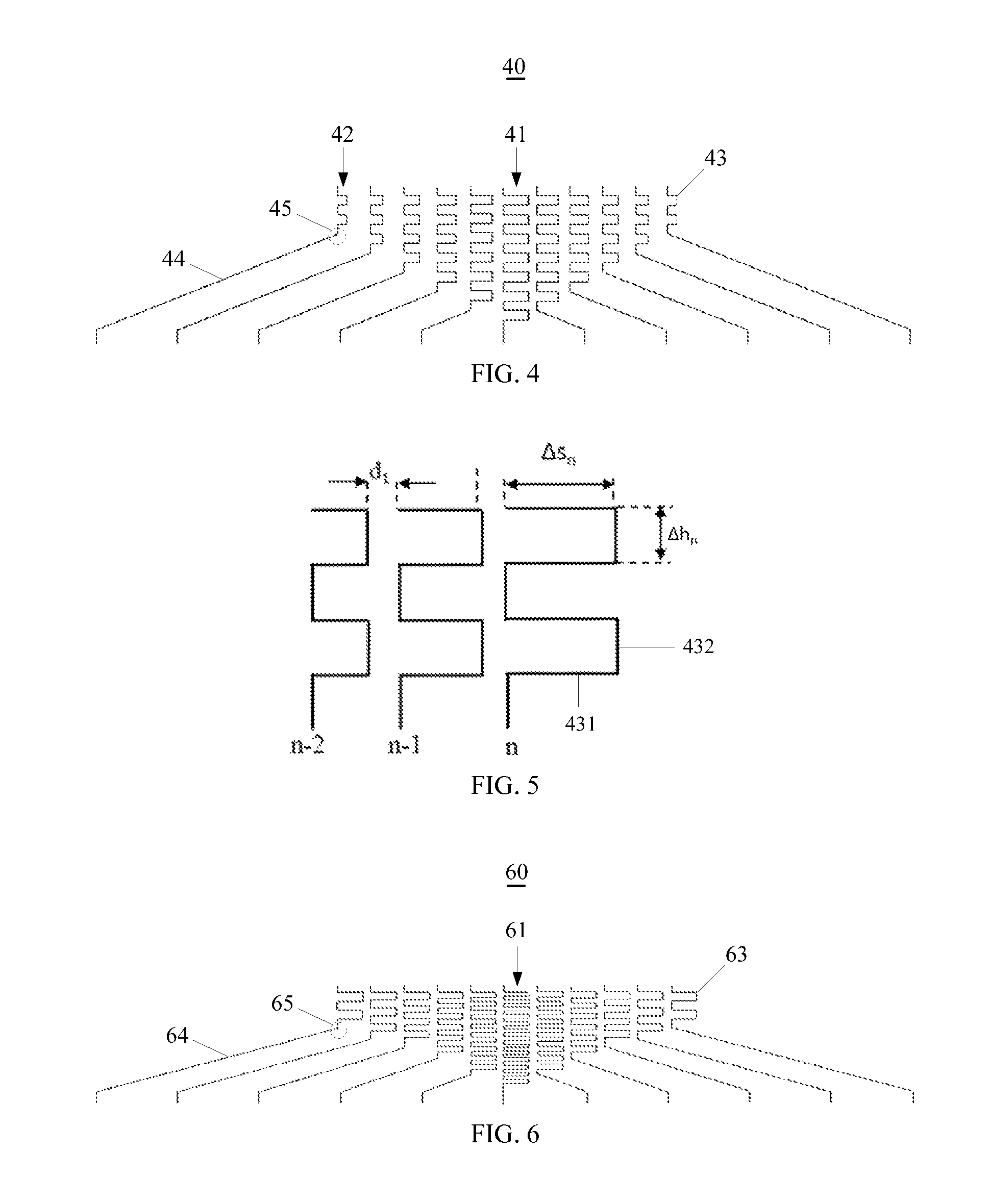
[0056]FIG. 4 is a schematic structural top view of a fan-out area according to the present invention, and FIG. 5 is a schematic partial structural view of three neighboring wires. Please refer to FIGS. 4 and 5 together:

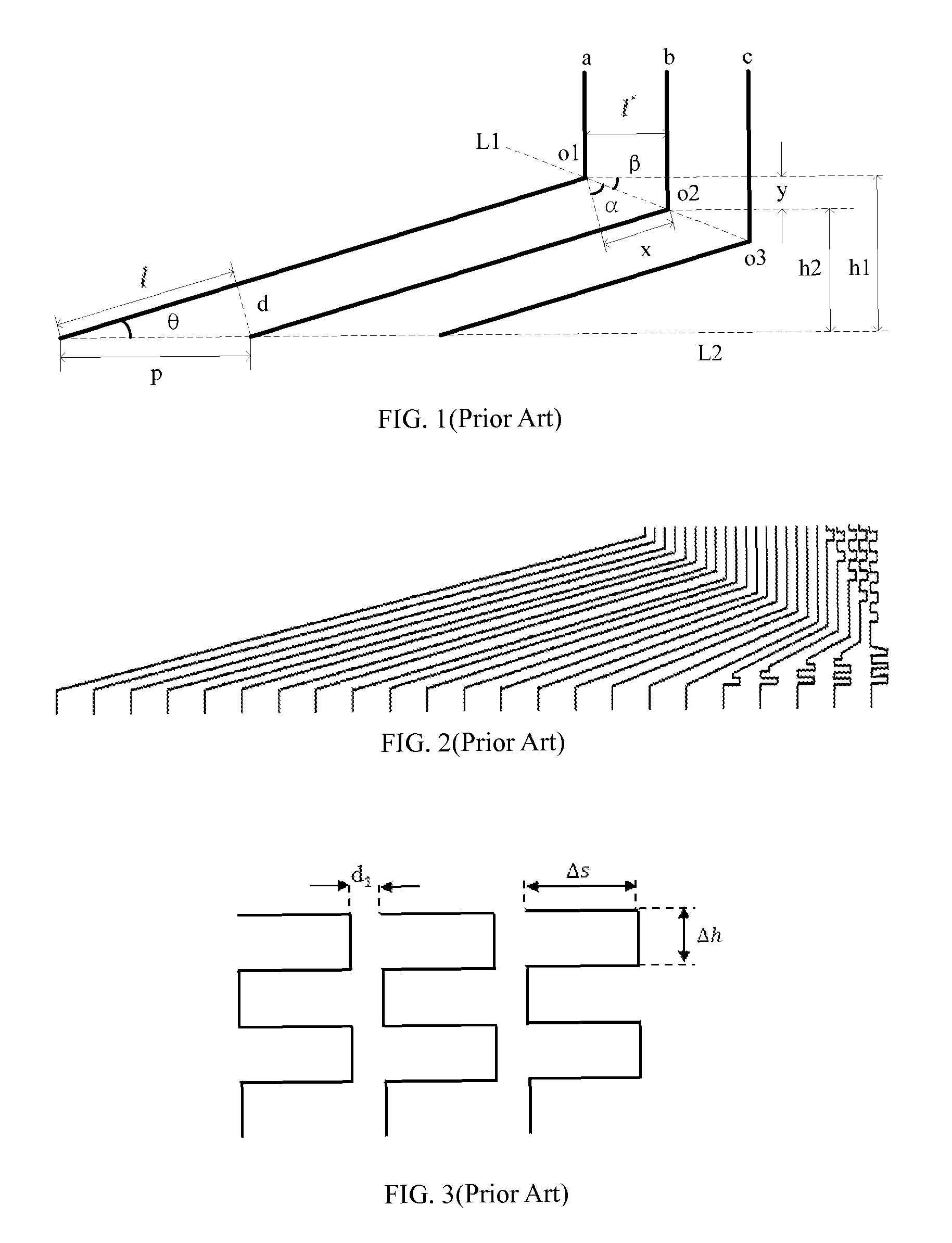
[0057]The fan-out area 40 includes a plurality of wires. The wires are classified into a middle wire 41 arranged at a middle region of the fan-out area 40 and a plurality of fan-out wires 42 arranged at two sides of the middle wire 41. In the illustrated embodiment, the fan-out wires 42 are symmetrically arranged at the two sides of the middle wire 41, and any two neighboring wires of the wires have a distance d1 same as that of another two neighboring wires of the wires.

[0058]The middle wire 41 and the fan-out wires 42 each are disposed with at least one first wire pattern 43. Moreover, along each of directions toward the middle wire 41, widths of the first wire patterns 43 of different wires (including the middle wire 41 and the fan-out wires 42) are successively in...

second embodiment

[0068]FIG. 6 is a schematic structural top view of a fan-out area according to the present invention, and FIG. 7 is a schematic partial structural view of three neighboring wires in FIG. 6. Please refer to FIGS. 6 and 7 together:

[0069]The fan-out area 60 in the second embodiment will be described on the basis of the first embodiment illustrated in FIGS. 4 and 5, a difference is that: in the fan-out area 60 of this embodiment, along each of the directions toward the middle wire 61, lengths of second sub-patterns 632 of different wires are successively decreased while widths of the second sub-patterns 632 of the different wires are kept unchanged, and lengths of first sub-patterns 631 of the different wires are the same. Preferably, the lengths of the second sub-patterns 632 of the different wires are successively decreased with a second amplitude. The above-mentioned first amplitude and the second amplitude are without necessarily mathematical relationship, and thus can be the same o...

third embodiment

[0075]FIG. 8 is a schematic structural top view of a fan-out area according to the present invention, and FIG. 9 is a schematic partial structural view of three neighboring wires in FIG. 8. Please refer to FIGS. 8 and 9 together:

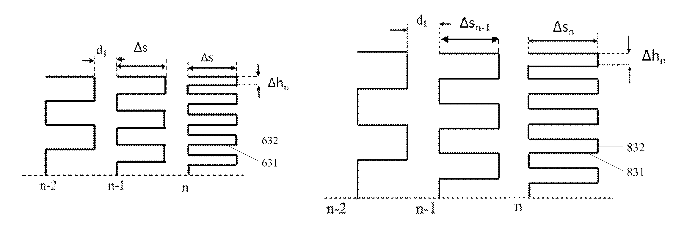
[0076]A fan-out area 80 in this embodiment will be described on the basis of the first embodiment as illustrated in FIGS. 4 and 5, and a difference is that: in the fan-out area 80 of this embodiment, along each of the directions toward the middle wire 81, lengths of second sub-patterns 832 of different wires are successively decreased and widths of the second sub-patterns 832 of the different wires are kept unchanged, and the lengths of the first sub-patterns 831 of the different wires are successively increased.

[0077]Likewise, by combining the expressions 1-13 through 1-16 ought to be satisfied by the width Δs and the length Δh of the arcuate patterns in the prior art with a route (rather than length) of the second wire pattern 84 and the turning part 85 of...


PUM

PropertyMeasurementUnit
lengthsaaaaaaaaaa
widthaaaaaaaaaa
lengthaaaaaaaaaa

Abstract

A liquid crystal display panel and a fan-out area thereof are provided. The fan-out area is arranged in a peripheral circuit area of the liquid crystal display panel and includes a middle wire and multiple fan-out wires arranged at two sides thereof. The middle wire and the fan-out wires each are disposed with at least one first wire pattern. Along each of directions toward the middle wire, widths of the first wire patterns of different wires are successively increased and / or lengths of the first wire patterns are successively decreased. The first wire patterns of a same wire have same width and length. Accordingly, the present invention can reduce the resistance differences among the wires in the fan-out area, color washout and non-uniform brightness caused by the resistance differences can be relieved or avoided, and is beneficial to the narrow border design of the liquid crystal display panel.

Description

TECHNICAL FIELD[0001]The present invention relates to the field of liquid crystal display technology, especially the field of wire routing technology in a peripheral circuit area of a liquid crystal display panel, and particularly to a liquid crystal display panel and a wire layout of a fan-out area thereof, so as to reduce resistance differences in the fan-out area.DESCRIPTION OF RELATED ART[0002]A liquid crystal display panel generally includes a display area and a peripheral circuit area. The display area has pixel units formed therein for image display. The peripheral circuit area has driver ICs and wires such as scan lines and data lines connected to the driver ICs formed therein. In order to decrease the peripheral circuit area and increase the display area, the wires generally are designed toward the driver ICs and thereby forming fan-out areas.[0003]In the fan-out area, the wires arranged at different positions with respect to the driver ICs would result in the wires having ...

Claims


Application Information

Patent Timeline
Patent Type & Authority Patents(United States)
IPC IPC(8): G02F1/1345
CPCG02F1/1345
Inventor WANG, CONGDU, PENG
Owner TCL CHINA STAR OPTOELECTRONICS TECH CO LTD
Why Eureka
Try Eureka