
Low maintenance nozzle mixer unit for roll nip lubrication

a technology of low maintenance and mixer unit, which is applied in the direction of filtration separation, separation processes, manufacturing tools, etc., can solve the problem of reducing the overall maintenance effort, and achieve the effect of reducing the maintenance effort and carrying out maintenan

Inactive Publication Date: 2017-02-14
PRIMETALS TECH AUSTRIA GMBH
View PDF16 Cites 0 Cited by
  • Summary
  • Abstract
  • Description
  • Claims
  • Application Information

AI Technical Summary

Benefits of technology

[0010]The object of the present invention is to specify a device for lubricating the cylinders of a roll stand in which the maintenance effort is as low as possible.
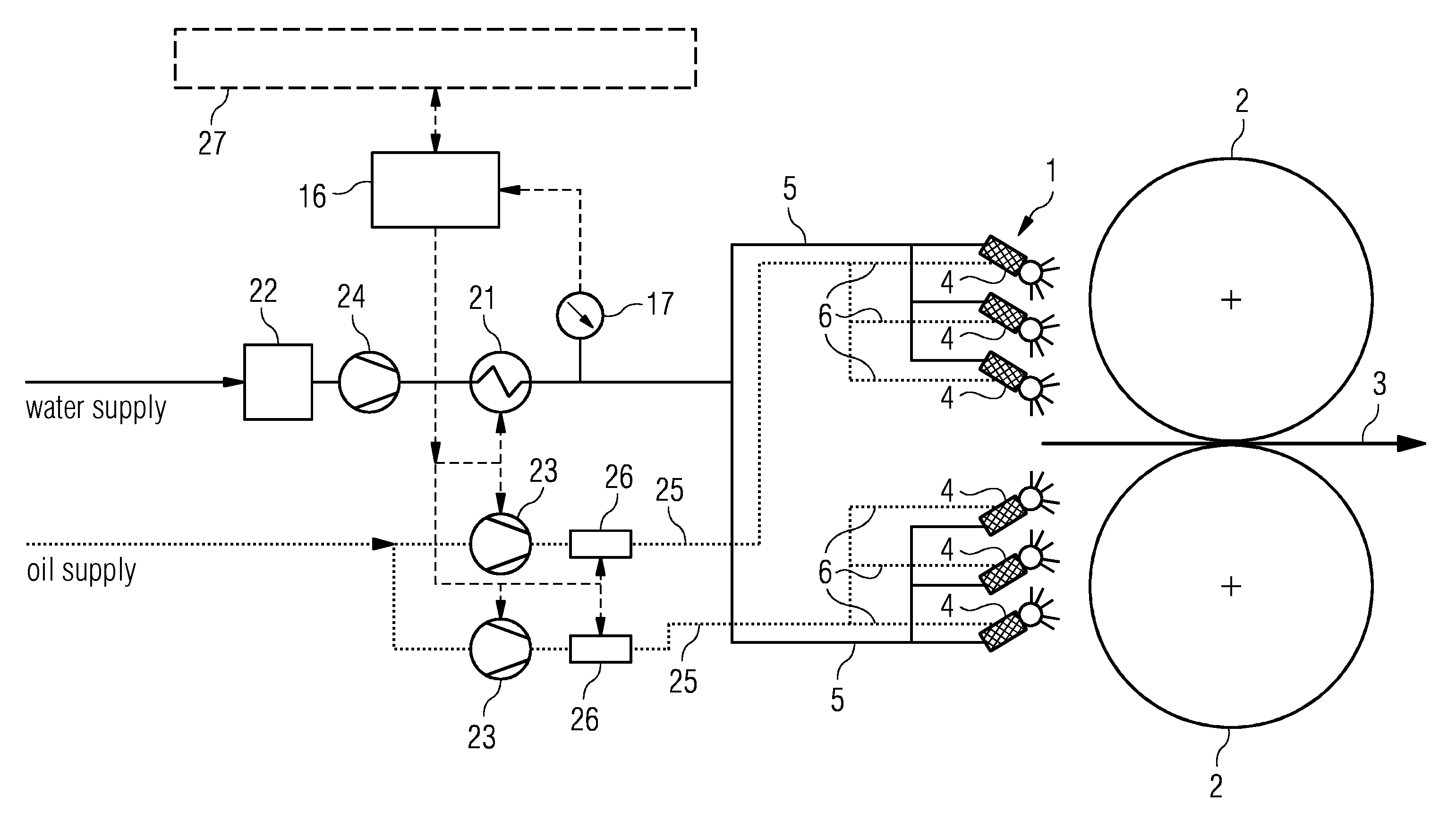
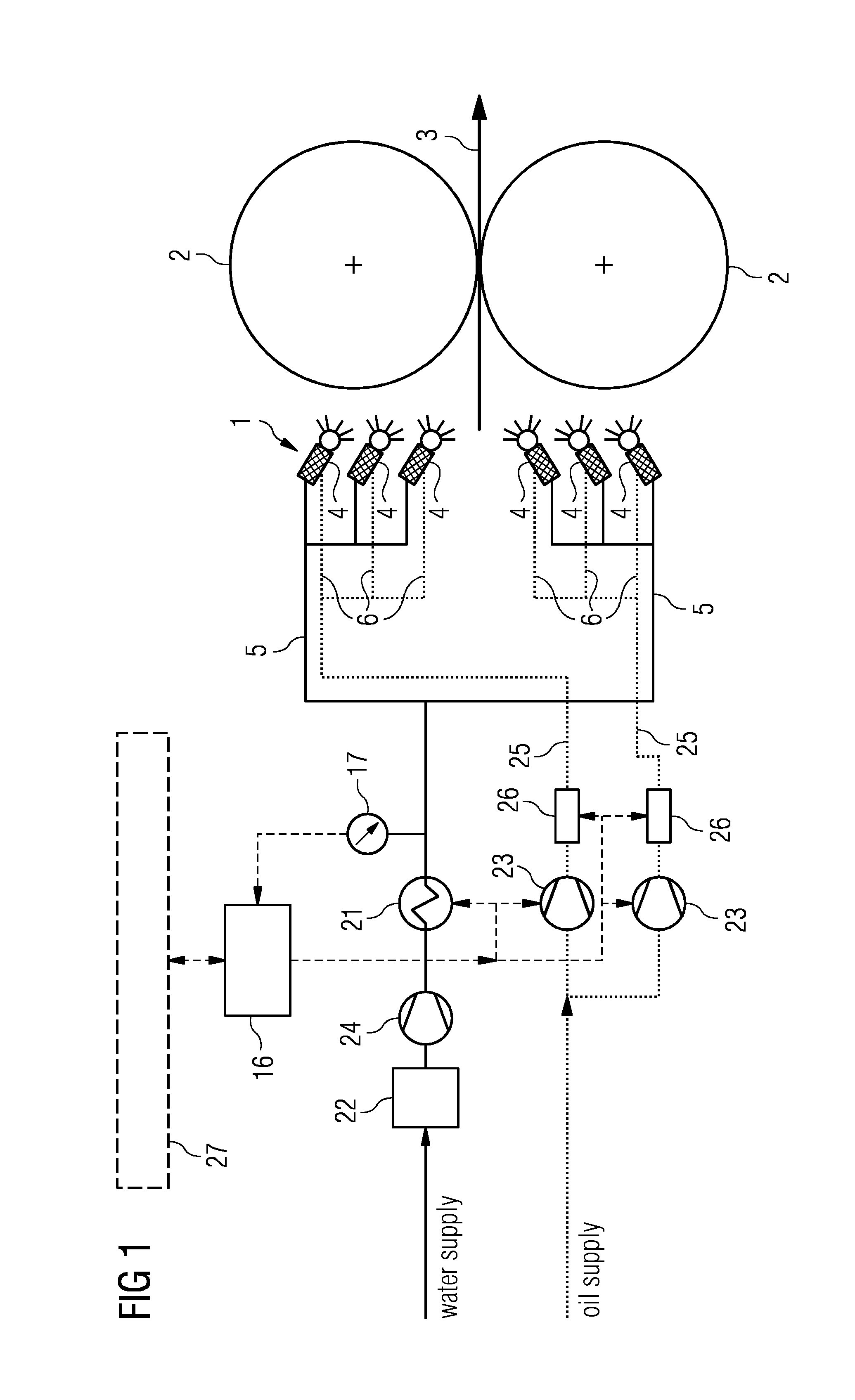
[0012]According to the basic idea of the invention, each mixer and nozzle are combined into one constructional unit, meaning that each spray nozzle is assigned a mixer unit. The emulsion is thus not created centrally and then distributed to a number of spray nozzles, but is created locally for each spray nozzle. This means that it is possible to produce the emulsion where it is also sprayed. This does away with long pipe lines between mixer and nozzle which, as a result of the long dwell time, are especially critical for contamination. Since the saponification forms less heavily in the roll nip lubrication system, cleaning has to be done less frequently. This means that overall the maintenance effort is lower.
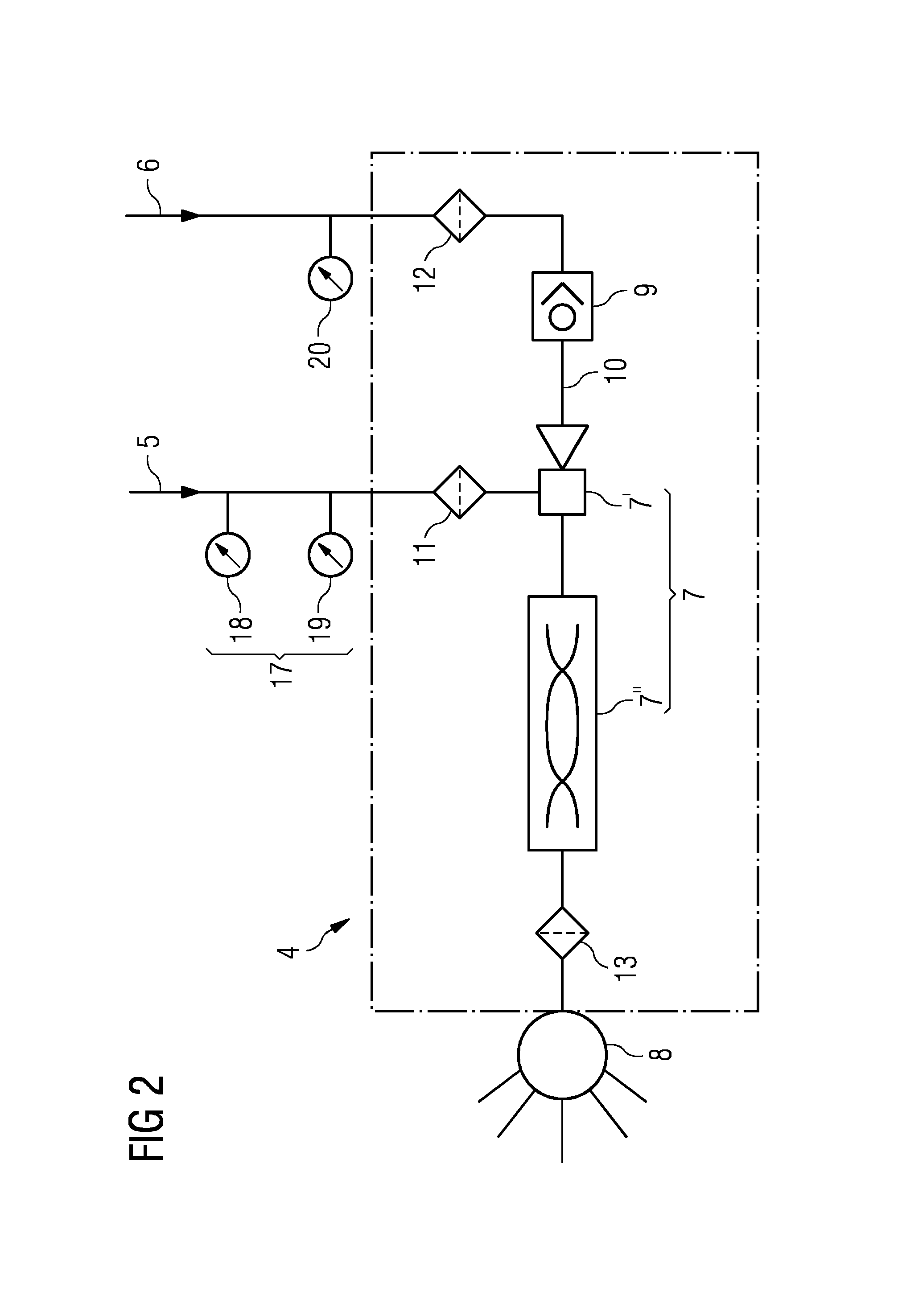
[0014]It is especially useful for mixer and spray nozzle to be integrated into one component. Thus there is no connecting line at all. The time the emulsion spends in the mixing and spray device is extremely short. A short dwell time means that the saponification is very small.
[0016]To avoid saponification residue it can be useful for the supply line of the oil to the mixing device to be routed via a stop valve provided in the nozzle mixer unit. This prevents water penetrating into the oil line during a cleaning interval in which the oil supply is actually interrupted and forming saponification there.
[0018]To further reduce the maintenance effort, it can be advantageous for a quick exchange device to be provided for each nozzle mixer unit. Such a quick exchange device can for example be realized so that the fitting of a nozzle mixer unit in a retaining device is made by means of a latching or snap-in connection, e.g. a bayonet lock. This enables the nozzle mixer unit to be changed manually very quickly during a maintenance shutdown. The removed nozzle mixer unit can be cleaned “off-line”, and maintenance carried out if required.

Problems solved by technology

This does away with long pipe lines between mixer and nozzle which, as a result of the long dwell time, are especially critical for contamination.
This means that overall the maintenance effort is lower.

Method used


Image

  • Low maintenance nozzle mixer unit for roll nip lubrication
  • Low maintenance nozzle mixer unit for roll nip lubrication
  • Low maintenance nozzle mixer unit for roll nip lubrication

Examples


Embodiment Construction

[0023]FIG. 1 shows a block diagram of an inventively embodied roll nip lubrication unit. A mixing and spray device 1 is formed from a number of nozzle mixer units 4. These nozzle mixer units 4 introduce an emulsion, made up of water and oil, into the roll nip. This is done by the nozzles 8 (see FIG. 2) of the nozzle mixer unit 4 spraying the emulsion onto the working cylinders 2 and / or onto the surface of the rolled strip 3.

[0024]Each nozzle mixer unit 4 is supplied with water via a first supply line 5 and with oil via a second supply line 6. The nozzle and mixer form one constructional unit.

[0025]The oil supply line to the mixing and spray devices 1 is routed in line bundles 25. The oil lines are supplied either by individual pump elements and / or via oil valves which operate in switched mode or continuously. Thus each nozzle mixer unit can have a common or individual oil flow applied to it, e.g. also 0%.

[0026]As can easily be seen from the diagram of FIG. 1, the oil and water are n...


PUM

PropertyMeasurementUnit
diameteraaaaaaaaaa
temperatureaaaaaaaaaa
volumeaaaaaaaaaa

Abstract

A device for lubricating the cylinders of a roll stand, in particular for roll nip lubrication in a roll stand for strip-shaped rolling stock. A mixture of water and oil is produced by a mixing and spraying device (1). The mixture is sprayed onto at least one of the cylinders (2) of the roll stand and / or to the surface of the rolling stock (3). The mixing and spraying device (1) include an arrangement of several nozzle mixer units (4). Water is guided thereto by a first supply line (5) and oil is guided thereto by a second supply line (6).

Description

CROSS-REFERENCE TO RELATED APPLICATIONS[0001]The present application is a 35 U.S.C. §§371 national phase conversion of PCT / EP2013 / 052370, filed Feb. 7, 2013, which claims priority of European Patent Application No. 12155484.4, filed Feb. 15, 2012, the contents of which are incorporated by reference herein. The PCT International Application was published in the German language.TECHNICAL FIELD[0002]The invention relates to a device for lubricating the cylinders of a roll stand, especially for roll nip lubrication in a roll stand for strip-shaped rolling stock, wherein a mixture made out of water and oil is produced by means of a mixing and spraying device and this mixture is sprayed onto at least one of the cylinders of the roll stand and / or onto the surface of the rolling stock.PRIOR ART[0003]It is known that, during the manufacturing of a metal strip, its surface quality can be improved when the coefficient of friction between working cylinders and rolling stock is reduced. When a l...

Claims


Application Information

Patent Timeline
Patent Type & Authority Patents(United States)
IPC IPC(8): B21B27/10B21B45/02B01D35/02
CPCB21B27/10B01D35/02B21B45/0242B21B45/0248B21B45/0251
Inventor BRAIDT, THOMASKARL, REINHARD
Owner PRIMETALS TECH AUSTRIA GMBH
Learn More