Adjustable planter disk

a planter disk and planter technology, applied in the field of planter disks, can solve the problems of insufficient operation, fouling or clogging of the port, and expensive and possibly dangerous electrical sensing units, and achieve the effect of reducing the tendency increasing the weight of the planter disk

Inactive Publication Date: 2017-02-21
SUNCAST TECH
View PDF28 Cites 3 Cited by
  • Summary
  • Abstract
  • Description
  • Claims
  • Application Information

AI Technical Summary

Benefits of technology

[0007]The present device is an adjustable planter disk for providing a false bottom within a planter. In some embodiments, the planter disk also provides a water reservoir within the bottom portion of a plant container for automatic watering of the plants supported by the planter disk. In general, the planter disk is constructed from a resin material in a circular shape having a first end that overlaps, or partially overlaps, a second end. The planter disk is constructed to include a plurality of sections connected with living hinges. In operation, the first end rotates over the top surface of the second end, flexing the living hinges to vary the outer diameter of the planter disk in order to create a disk insert for insertion within a variety of sizes of flower pots. Latches and / or catches are provided to allow the planter disk to be secured at the proper diameter. Along the peripheral edge of the planter disk is a rib. The rib creates a frictional contact point with the inside surface of a planter in order to provide a snug fit and structural integrity. In at least one embodiment, the center portion of the planter disk is raised. This construction causes the disk to expand in diameter slightly as weight on the planter disk is increased, reducing the tendency of the planter disk to slide down the inner surface of the planter. Additionally, along the peripheral edge of the circular disk are a plurality of water drainage / root growth apertures. These apertures allow excess water to drain into a reservoir created within the plant container and beneath the planter disk. The apertures also allow the roots of the plant(s) to grow through the apertures and into the water whereby water can be supplied to the plant(s) for extended periods. The planter disk may be used with planters of various sizes and shapes as small gaps around the periphery of the planter disc will not hamper its operation.

Problems solved by technology

Sensing self watering planters of this type have utilized expensive and possibly dangerous electrical sensing units.
Furthermore, roots of the plant are hydrotropic, so they tend to grow towards the source of water; thus the plant roots will grow down through the soil to the inlet port of the planter and foul or clog the port such that it does not operate properly.
Another disadvantage of self watering planters from the prior art is that the tube connecting the sensor element to the water reservoir frequently extends above the level of the planter and is not aesthetically pleasing.
This not only mars the beauty of the plant, but in public areas such as restaurants and hotel lobbies, frequently leads to the sensor being displaced or broken by passers-by or curious individuals.
Giving the roots too much room will cause the roots to spread too far and the excessive amount of soil may not drain properly.
Thus, what is lacking in the art is an adjustable planter disk for placement within a planter.

Method used


Image

  • Adjustable planter disk
  • Adjustable planter disk
  • Adjustable planter disk

Examples


Embodiment Construction

[0022]While the present invention is susceptible of embodiment in various forms, there is shown in the drawings and will hereinafter be described a presently preferred, albeit not limiting, embodiment with the understanding that the present disclosure is to be considered an exemplification of the present invention and is not intended to limit the invention to the specific embodiments illustrated.

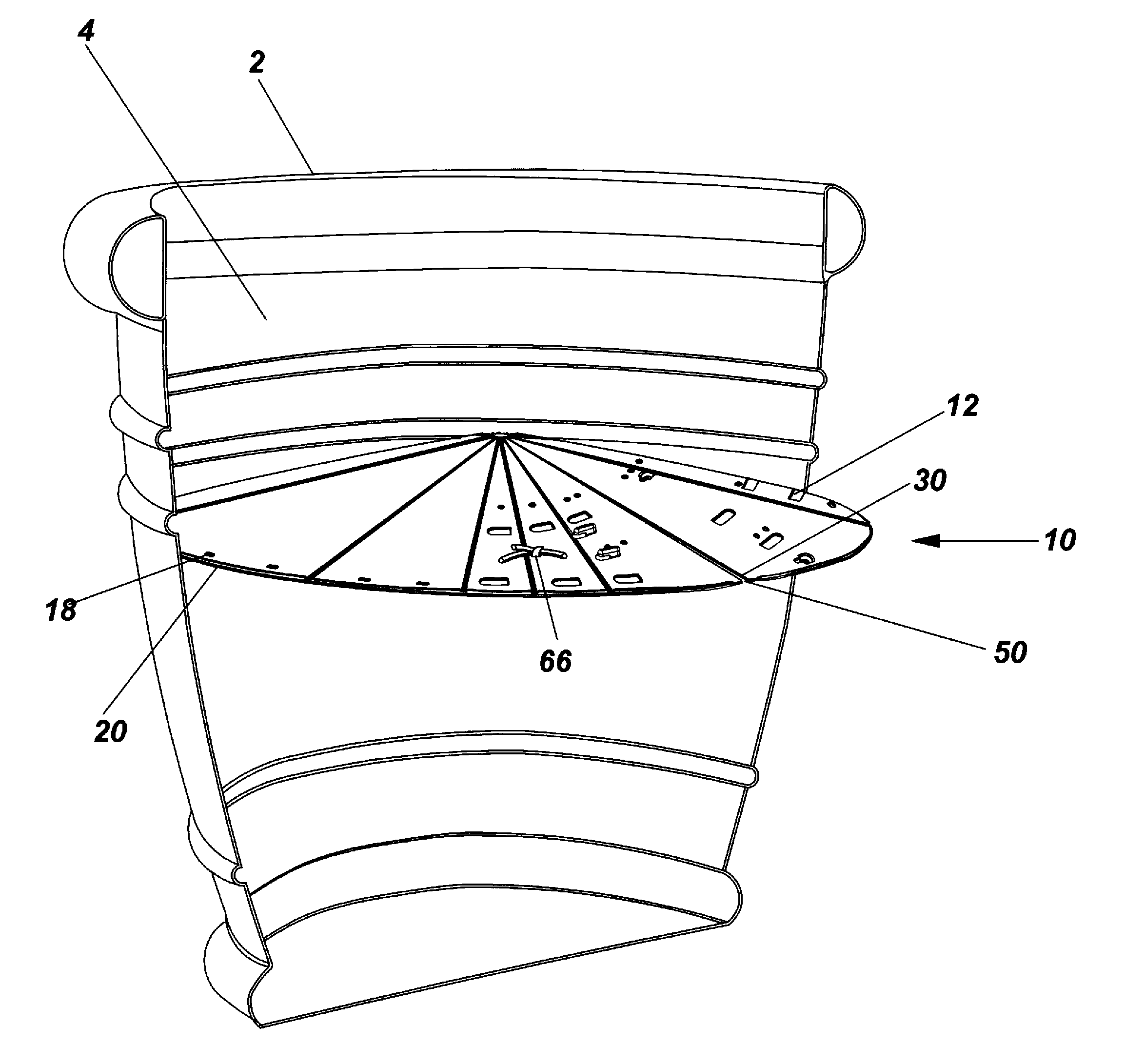
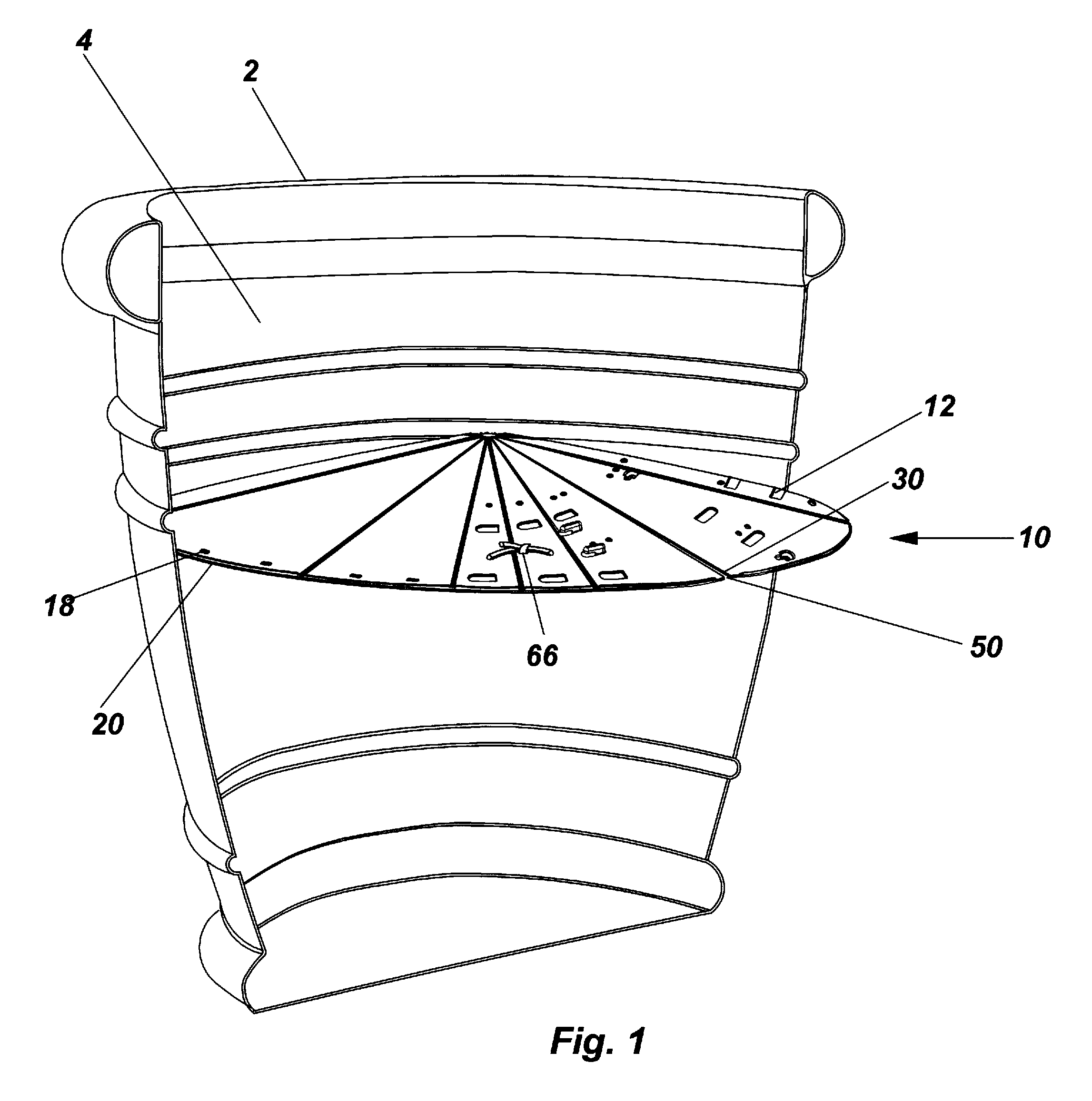
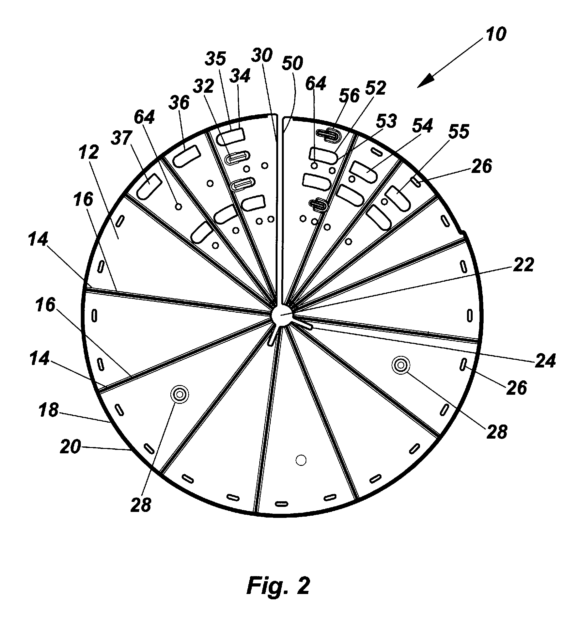
[0023]Now referring to FIGS. 1-5, the adjustable planter disk insert 10 is a circular disk comprised of a single resin composite sheet 12 (referred to herein as sheet) having a first terminating end 30 that overlaps, or partially overlaps, a second terminating end 50, aptly shown in FIGS. 4 and 5. The sheet 12 includes a peripheral edge 18 and center hole 22. The first terminating end 30 rotates overtop the second terminating end 50 to create differing radii in order to create an adjustable planter disk insert 10 for insertion within a flower pot 2. The adjustable planter disk insert 10, the...


PUM


Abstract

An adjustable planter disk comprised of a circular disk constructed of a single resin composite sheet is disclosed. The sheet has a first terminating end that overlaps, or partially overlaps, a second terminating end. The sheet includes a peripheral edge and center hole. The first terminating end rotates overtop the second terminating end and latches thereto using a pair of hooks on the first terminating end and a series of corresponding holes on the second terminating end to create differing radii. The sheet is divided into a plurality of sectors, each sector including a living hinge that runs from the peripheral edge to the center that allows for the first terminating end to extend and contract. Additionally, along the peripheral edge of the circular are a plurality of water drainage holes.

Description

FIELD OF THE INVENTION[0001]This invention is directed to the field of flower pot accessories, and more particularly to an adjustable planter disk for placement within a planter.BACKGROUND OF THE INVENTION[0002]Capillary action is the ability of a liquid to flow in narrow spaces without the assistance of, and in opposition to, external forces like gravity. Capillary action occurs because water is sticky, due to the forces of cohesion (water molecules stay close together) and adhesion (water molecules are attracted and stick to other substances). It is defined as the movement of water within the spaces of a porous material due to the forces of adhesion, cohesion, and surface tension.[0003]Plants and trees couldn't thrive without capillary action; capillary action is important for moving water and all of the nutrients dissolved within it to the plant and throughout it. Plants grow roots into the soil which are capable of absorbing and carrying the water from the soil up into the plant...

Claims


Application Information

Patent Timeline
Patent Type & Authority Patents(United States)
IPC IPC(8): A01G27/02A01G27/00A01G9/02
CPCA01G27/008A01G9/02A01G27/00A01G27/02
Inventor RUSSELL, BRIAN J.VOGLER, MICHAEL R.THUMA, MICHAEL
Owner SUNCAST TECH
Why Eureka
Try Eureka