
Artifact control and miniaturization of the safe direct current stimulator for neural prostheses

a direct current stimulator and neural prosthesis technology, applied in the field of neural prosthesis, can solve the problems of limited neural prosthesis, biological unsafe dc stimulation, and other neural prosthesis applications that have substantial difficulties in achieving effective treatment with excitation alon

Active Publication Date: 2017-02-21
THE JOHN HOPKINS UNIV SCHOOL OF MEDICINE
View PDF10 Cites 9 Cited by
  • Summary
  • Abstract
  • Description
  • Claims
  • Application Information

AI Technical Summary

Benefits of technology

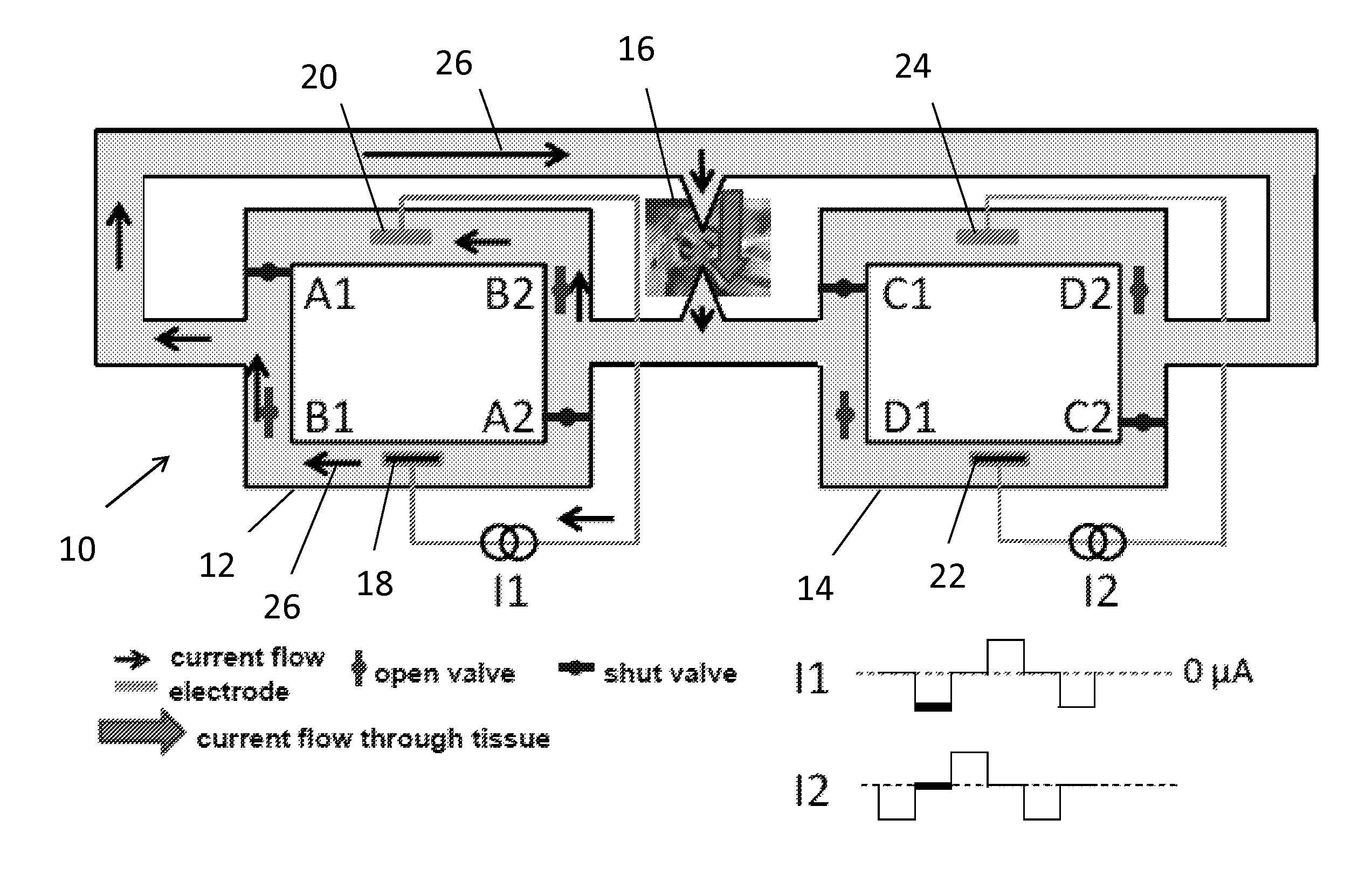
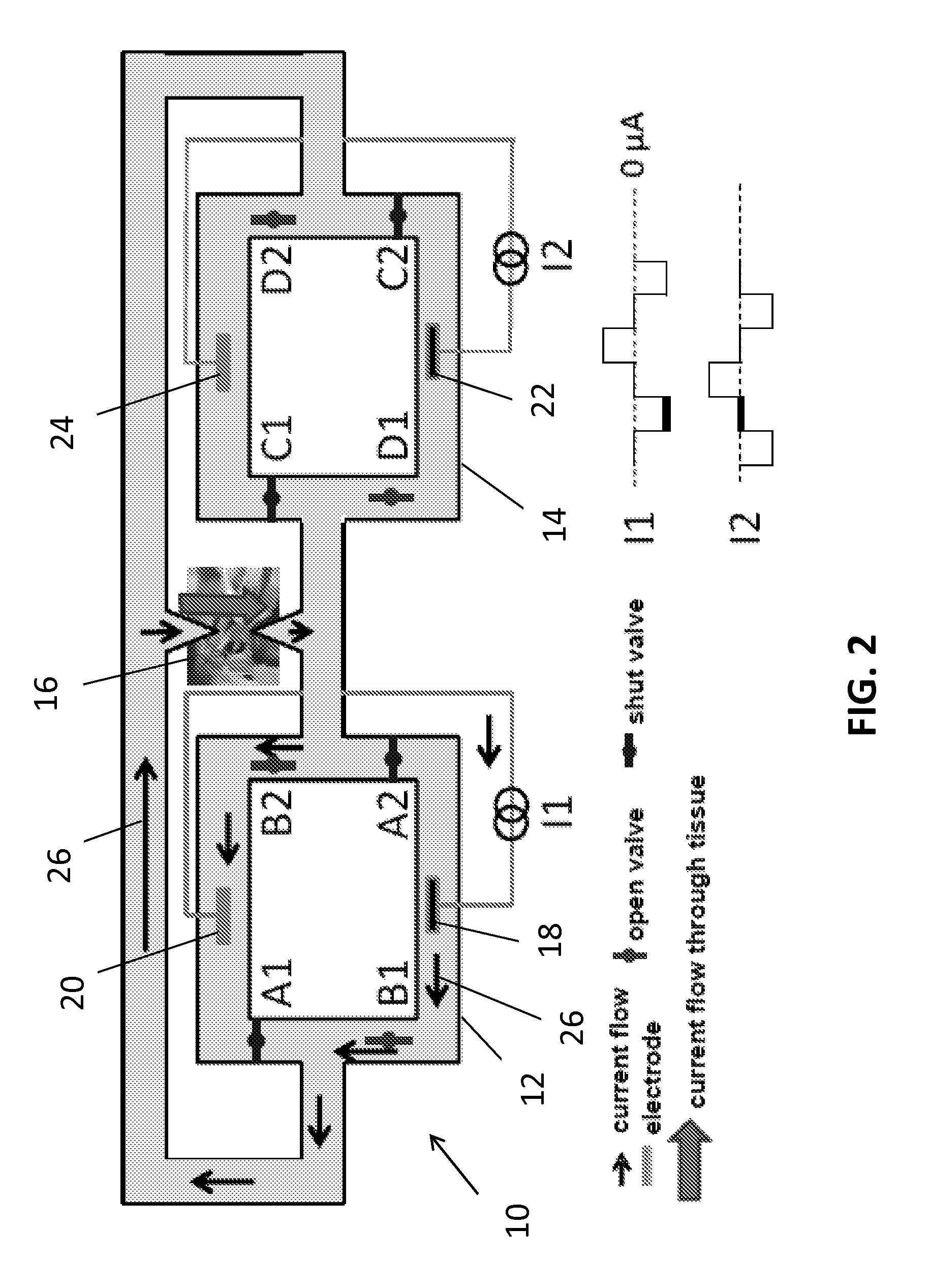
The patent describes a system that works in two phases. The first phase controls the output of ions to tissue, while the second phase undergoes valve transitions without affecting the output of the device. As the valves in the second phase transition, the system switches electronically from the first system to the second, allowing the first system to switch its valves without interfering with the device output. This ensures a smooth output of ions from the device, regardless of the speed at which the valves transition.

Problems solved by technology

While effective in treating some neurological disorders, neural prostheses are limited because they can excite neurons but not efficiently inhibit them.
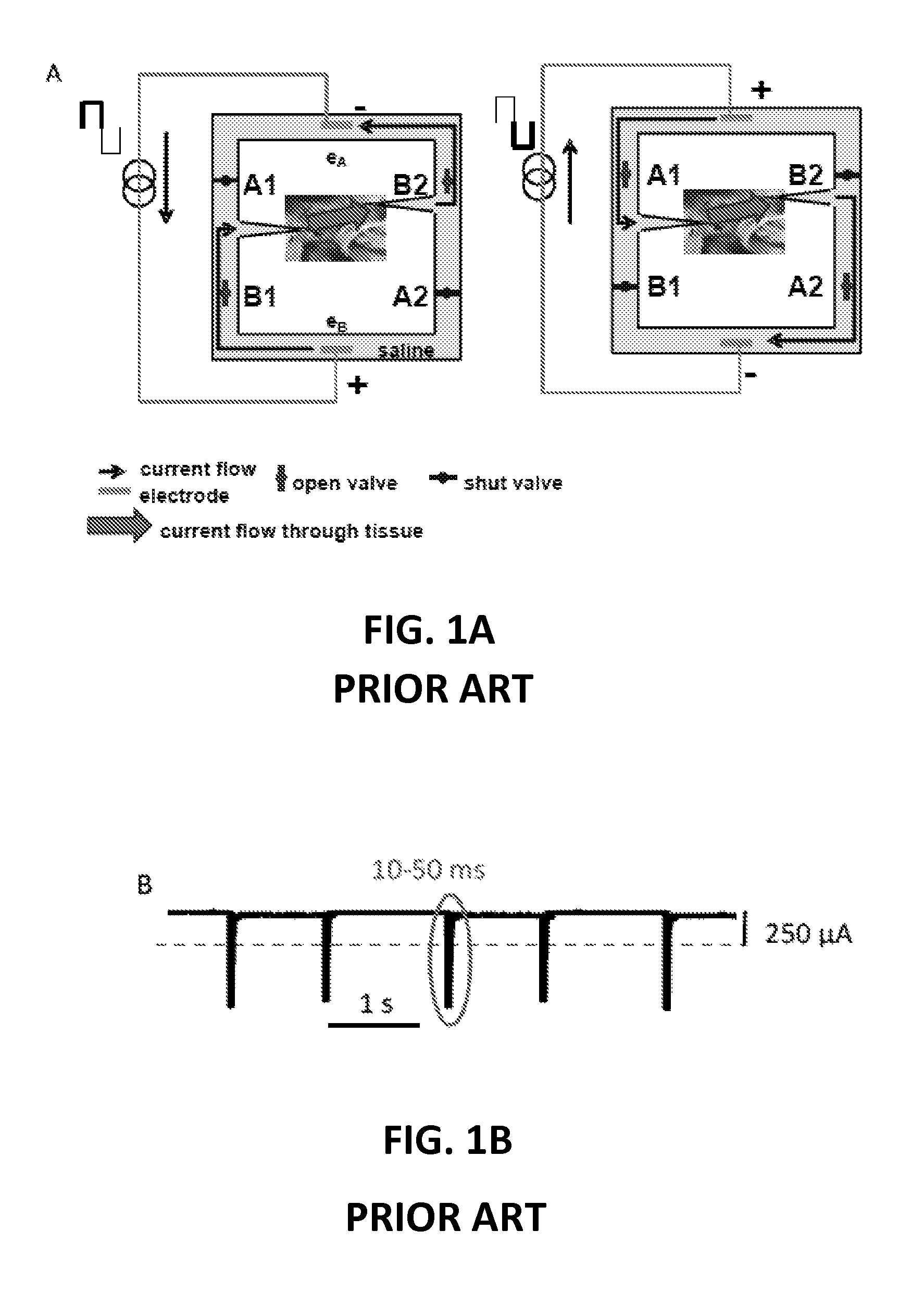
Direct current (DC) applied to a metal electrode in contact with neural tissue can excite or inhibit neural activity; however, DC stimulation is biologically unsafe because it causes electrochemical reactions at the metal electrode-tissue interface.
While cochlear and retinal prostheses use AC pulses to encode sensory information by modulating firing rate of the afferent fibers above their spontaneous activity, other neural prosthesis applications have substantial difficulties achieving effective treatment with excitation alone.
Any interruption in the DC current flow however will cause the undesirable volley of neural activity in the target neurons.

Method used


Image

  • Artifact control and miniaturization of the safe direct current stimulator for neural prostheses
  • Artifact control and miniaturization of the safe direct current stimulator for neural prostheses
  • Artifact control and miniaturization of the safe direct current stimulator for neural prostheses

Examples


Embodiment Construction

[0024]The presently disclosed subject matter now will be described more fully hereinafter with reference to the accompanying Drawings, in which some, but not all embodiments of the inventions are shown. Like numbers refer to like elements throughout. The presently disclosed subject matter may be embodied in many different forms and should not be construed as limited to the embodiments set forth herein; rather, these embodiments are provided so that this disclosure will satisfy applicable legal requirements. Indeed, many modifications and other embodiments of the presently disclosed subject matter set forth herein will come to mind to one skilled in the art to which the presently disclosed subject matter pertains having the benefit of the teachings presented in the foregoing descriptions and the associated Drawings. Therefore, it is to be understood that the presently disclosed subject matter is not to be limited to the specific embodiments disclosed and that modifications and other ...


PUM


Abstract

An embodiment in accordance with the present invention provides a device and method to deliver direct ionic current safely to target neural tissue, while also eliminating interruptions in the output of the device that can result from the non-ideal operation of the valves used to control the current flow in the device. The device includes two valve-operated systems that work in tandem. The first and second current producing systems are configured to be used together in order to eliminate the periodic interruptions in current flow. In use, one system drives current through the target tissue, while the other system closes all of the valves first and then opens its valves in sequence. This intermediate step of closing all of the valves prevents unintended current shunts through either system. The device also includes two conductors to direct the flow of direct current into the target tissue.

Description

CROSS REFERENCE TO RELATED APPLICATIONS[0001]This application is a 35 U.S.C. §371 U.S. national entry of International Application PCT / US2012 / 070860 having an international filing date of Dec. 20, 2012, which claims the benefit of U.S. Provisional Application No. 61 / 577,821, filed Dec. 20, 2011, the content of each of the aforementioned applications is herein incorporated by reference in their entirety.GOVERNMENT SUPPORT[0002]This invention was made with government support under NIH R01DC009255 awarded by the National Institute of Health. The government has certain rights in the invention.FIELD OF THE INVENTION[0003]The present invention relates generally to neural stimulation. More particularly, the present invention relates to a device and method for delivering DC current to target tissue.BACKGROUND OF THE INVENTION[0004]While effective in treating some neurological disorders, neural prostheses are limited because they can excite neurons but not efficiently inhibit them. Direct cu...

Claims


Application Information

Patent Timeline
Patent Type & Authority Patents(United States)
IPC IPC(8): A61N1/36A61B5/11A61N1/32A61N1/44A61N1/20A61N1/30
CPCA61N1/325A61N1/20A61N1/303A61N1/32A61N1/3605A61N1/44
Inventor FRIDMAN, GENE YEVGENYDELLA SANTINA, CHARLES COLEMAN
Owner THE JOHN HOPKINS UNIV SCHOOL OF MEDICINE
Learn More