In-vehicle structure for inverter and bracket unit for inverter

a technology of inverter and inverter, which is applied in the direction of battery/cell propulsion, electric devices, transportation and packaging, etc., can solve the problems of large electromagnetic noise generated by inverter configured to supply current to the drive motor, relatively strong electromagnetic noise (radio noise), etc., and achieve effective restraint of the inductance of braided wires

Active Publication Date: 2017-02-21
TOYOTA JIDOSHA KK
View PDF14 Cites 1 Cited by
  • Summary
  • Abstract
  • Description
  • Claims
  • Application Information

AI Technical Summary

Benefits of technology

[0008]The inverter configured to supply current to the drive motor generates large electromagnetic noise. In view of this, in order to effectively restrain high frequency noise, an inductance of a conductive material that connects the inverter to the body should be lowered. The present specification provides such a technique that, when an inverter is fixed to a vehicle by use of a damping bush, an inductance of a conductive material configured to electrically connect a case of the inverter to a body together with a fixing structure (an in-vehicle structure) for the inverter is reduced.
[0009]According to one technique described in the present specification, it is possible to embody an in-vehicle structure for an inverter configured to supply electric power to a drive motor. The technique can reduce an inductance of a conductive material configured to electrically connect a case of the inverter to a body by ingeniously using a bracket to be used for fixing the inverter. The in-vehicle structure employs a bracket made of a metal plate, so as to fix the inverter. A damping bush is fitted between the bracket and either one of the case of the inverter and the body. As described above, the damping bush is generally made of an insulator. A braided wire is used to electrically connect the case of the inverter to the body. In the in-vehicle structure described in the present specification, the braided wire is wired along the metal plate of the bracket. Note that the “vehicle” to which the inverter is fixed encompasses not only the body of the vehicle and a frame thereof but also an engine unit and a transmission that have been already fixed to the frame and are maintained equipotential with the body. That is, the in-vehicle structure of the present specification includes fixing the inverter to the engine unit or the transmission.
[0010]When high-frequency current flows through the braided wire and a magnetic field occurs around the braided wire, induction current flows through the metal plate of the bracket along the braided wire. The induction current generates a magnetic field. The magnetic field of the induction current is in a reverse direction to the magnetic field of the braided wire, so as to offset the magnetic field of the braided wire. When the magnetic field of the braided wire is offset, an inductance of the braided wire is reduced. The technique described in the present specification reduces the inductance of the braided wire by use of the metal plate of the bracket for fixing the inverter.
[0012]The damping bush often includes a bush main body made of an insulator, and a metal fitting made of metal, joined to the bush main body and making contact with the case (or a vehicle-side structure). In this case, it is preferable that the one end of the braided wire be electrically and mechanically connected to the metal fitting of the damping bush, and the other end thereof be electrically and mechanically connected to the bracket. That is, it is preferable that the bracket, the damping bush, and the braided wire be assembled in advance before they are attached to the case of the inverter, so as to constitute one unit. When the bracket, the damping bush, and the braided wire are unitized, it is possible to simplify an assembling operation of the bracket, the damping bush, and the braided wire to the case of the inverter.
[0015]When the bracket unit is used, the metal fitting makes contact with the case of the inverter (or the vehicle). Vibration of the vehicle is absorbed by the bush main body between the first fixing portion and the metal fitting. The bracket unit achieves mechanical fixation and electrical connection of the inverter to the vehicle at the same time. It is not necessary to individually perform fixation and electrical connection of the inverter. Note that the braided wire is flat, and a flat surface thereof is preferably opposed to the metal plate (the connection portion) of the bracket. When the flat braided wire faces the flat bracket, induction current is easy to occur in the bracket, so that the inductance of the braided wire is restrained effectively.
[0016]According to the technique described in the present specification, it is possible to reduce the inductance of the braided wire that electrically connects the inverter to the vehicle, and to fix the inverter to the vehicle via the damping bush. Technical details described in the present specification and further improvements thereof are described in the following “DETAILED DESCRIPTION OF EMBODIMENTS”.

Problems solved by technology

The inverter configured to supply electric power to the drive motor in the electrically-driven vehicle deals with large electric power, and generates relatively strong electromagnetic noise (radio noise).
The inverter configured to supply current to the drive motor generates large electromagnetic noise.

Method used


Image

  • In-vehicle structure for inverter and bracket unit for inverter
  • In-vehicle structure for inverter and bracket unit for inverter
  • In-vehicle structure for inverter and bracket unit for inverter

Examples


Embodiment Construction

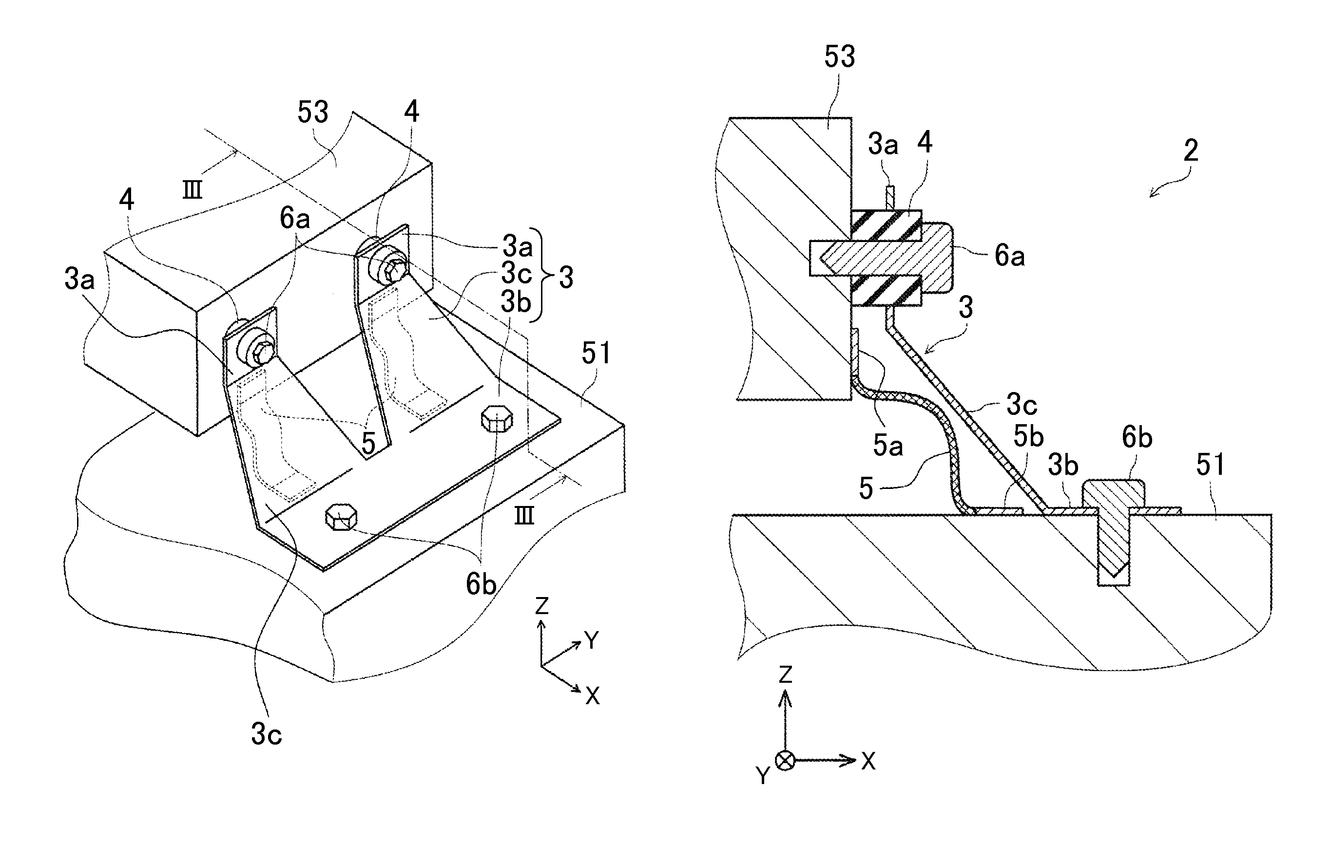
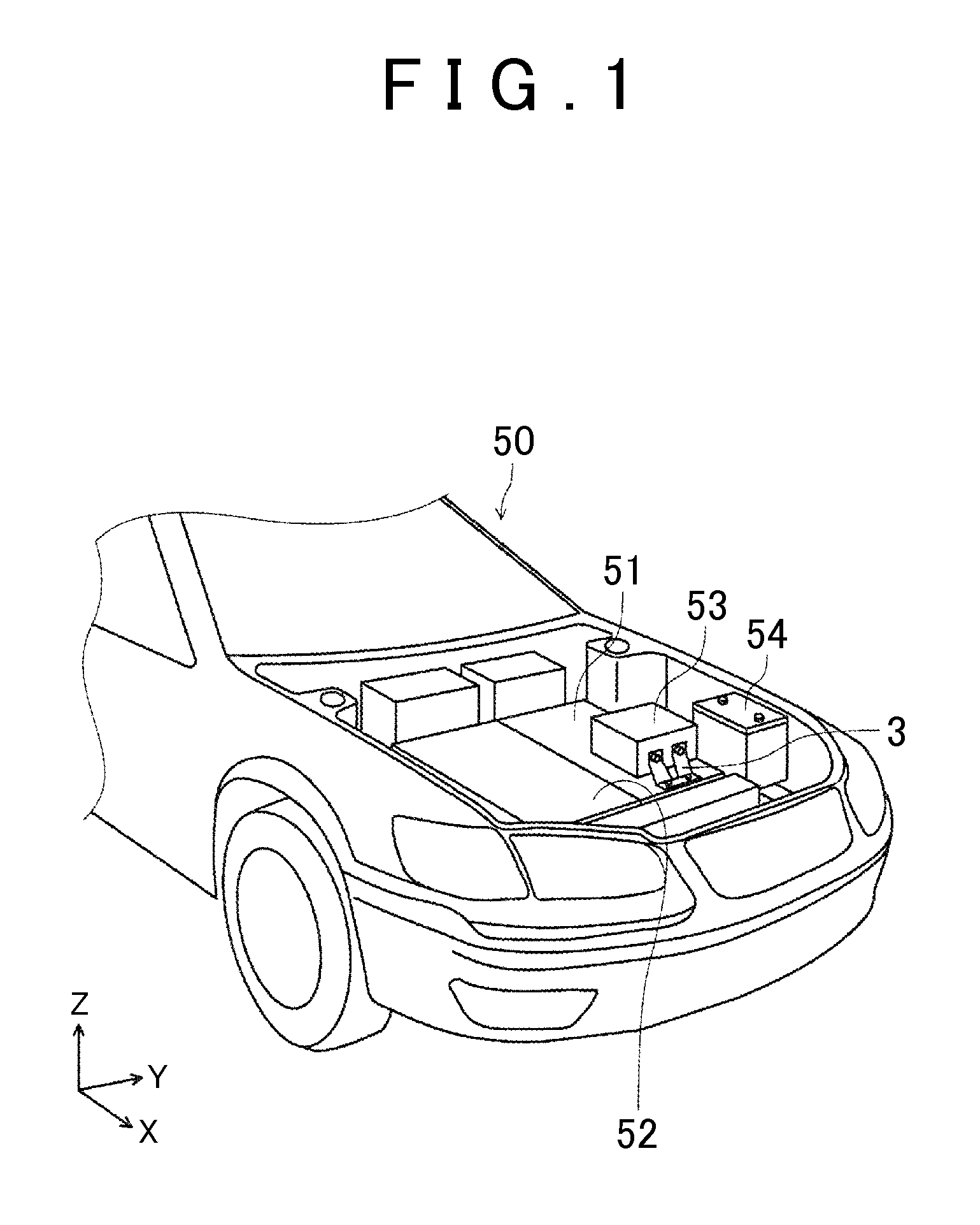
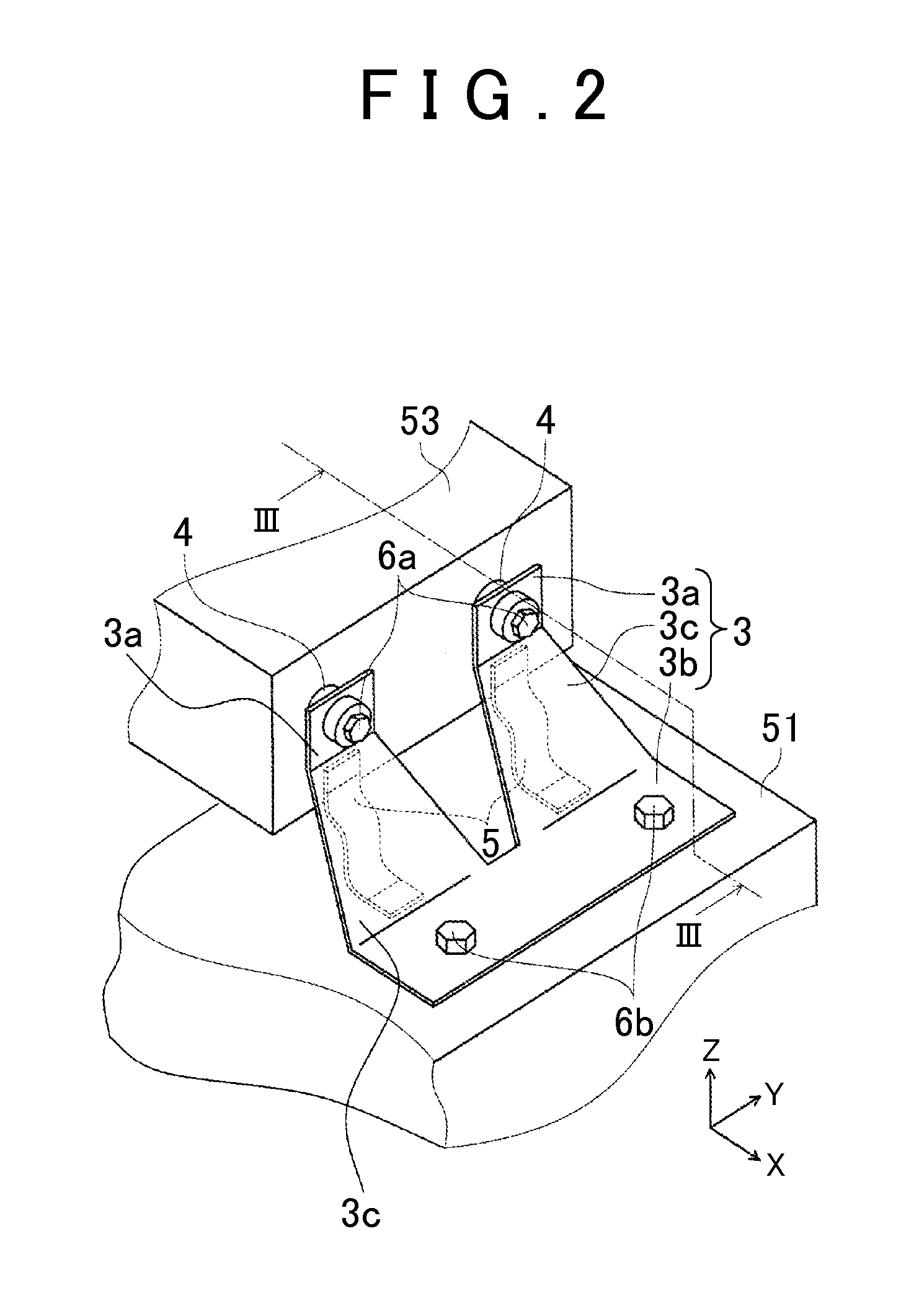
[0022]The following describes an in-vehicle structure for an inverter according to an embodiment with reference to the drawings. First described is an example of a device layout in an engine compartment of an electrically-driven vehicle. The electrically-driven vehicle in the present embodiment is, more specifically, a hybrid vehicle including an engine and a motor for driving. FIG. 1 is a perspective view illustrating a device layout in an engine compartment 50 of the hybrid vehicle. The engine compartment 50 on a vehicle front side is provided with an engine 52, a transmission 51 including a motor and gears therein, a sub-battery 54, and an inverter 53 configured to convert electric power of a main battery (not shown) into alternating current so as to supply the alternating current to the motor. Note that other various devices are provided in the engine compartment 50, but those devices are not illustrated herein. The engine 52 and the transmission 51 are fixed to a side frame (no...


PUM


Abstract

An in-vehicle structure for an inverter includes a bracket, a damping bush, and a braided wire. The bracket is made of a metal plate, and serves as a metal fitting for fixing the inverter to a transmission (a vehicle). The damping bush is fitted between the bracket and either one of a case of the inverter and the transmission. The damping bush is made of an insulator. The braided wire electrically connects the case of the inverter to the transmission. The braided wire is wired along the metal plate of the bracket.

Description

INCORPORATION BY REFERENCE[0001]The disclosure of Japanese Patent Application No. 2014-087319 filed on Apr. 21, 2014 including the specification, drawings and abstract is incorporated herein by reference in its entirety.BACKGROUND OF THE INVENTION[0002]1. Field of the Invention[0003]The present invention relates to an in-vehicle structure for an inverter configured to supply electric power to a drive motor, and a bracket unit configured to fix an inverter to a vehicle.[0004]2. Description of Related Art[0005]An automobile including an electrically-driven vehicle is generally configured such that a potential of its body is often set to an electric ground potential of an in-vehicle electric apparatus. The in-vehicle electric apparatus is electrically connected to the body, and is maintained equipotential (a ground potential) with the body. Since a case of the electric apparatus is made of a conductive metal in general, if the electric apparatus is fixed to the body or a frame of the v...

Claims


Application Information

Patent Timeline
Patent Type & Authority Patents(United States)
IPC IPC(8): H05K7/02B60L11/18B60L11/14B60L3/00H05K7/04B60R16/023B60L50/16
CPCB60R16/0238B60L3/003B60L3/0046B60L11/14B60L11/1803B60L2210/40B60L2270/145B60L2270/147B60L50/16B60L50/51Y02T10/70Y02T10/7072Y02T10/72
Inventor SAKAMOTO, YUSUKE
Owner TOYOTA JIDOSHA KK
Why Eureka
Try Eureka