In canopy bleed air actuator with mesh vent

a mesh vent and actuator technology, applied in emergency apparatus, parachutes, transportation and packaging, etc., can solve the problems of loss of control and landing accuracy, and the lack of necessary accuracy of known systems

Active Publication Date: 2017-02-21
EARTHLY DYNAMICS LLC
View PDF17 Cites 6 Cited by
  • Summary
  • Abstract
  • Description
  • Claims
  • Application Information

AI Technical Summary

Benefits of technology

[0007]The present invention relates to an actuator system to control the flight path of a parafoil used in combination with upper surface canopy spoilers created by vents or apertures in the upper canopy. A mesh member is placed on top of the canopy to cover the vents and allow for deformation of the fabric below the mesh member, without deforming the shape of the canopy. The physical ...

Problems solved by technology

These known control lines create aerodynamic drag and can become tangled or damaged upon deployment resulting in loss of control and la...

Method used


Image

  • In canopy bleed air actuator with mesh vent
  • In canopy bleed air actuator with mesh vent
  • In canopy bleed air actuator with mesh vent

Examples


Embodiment Construction

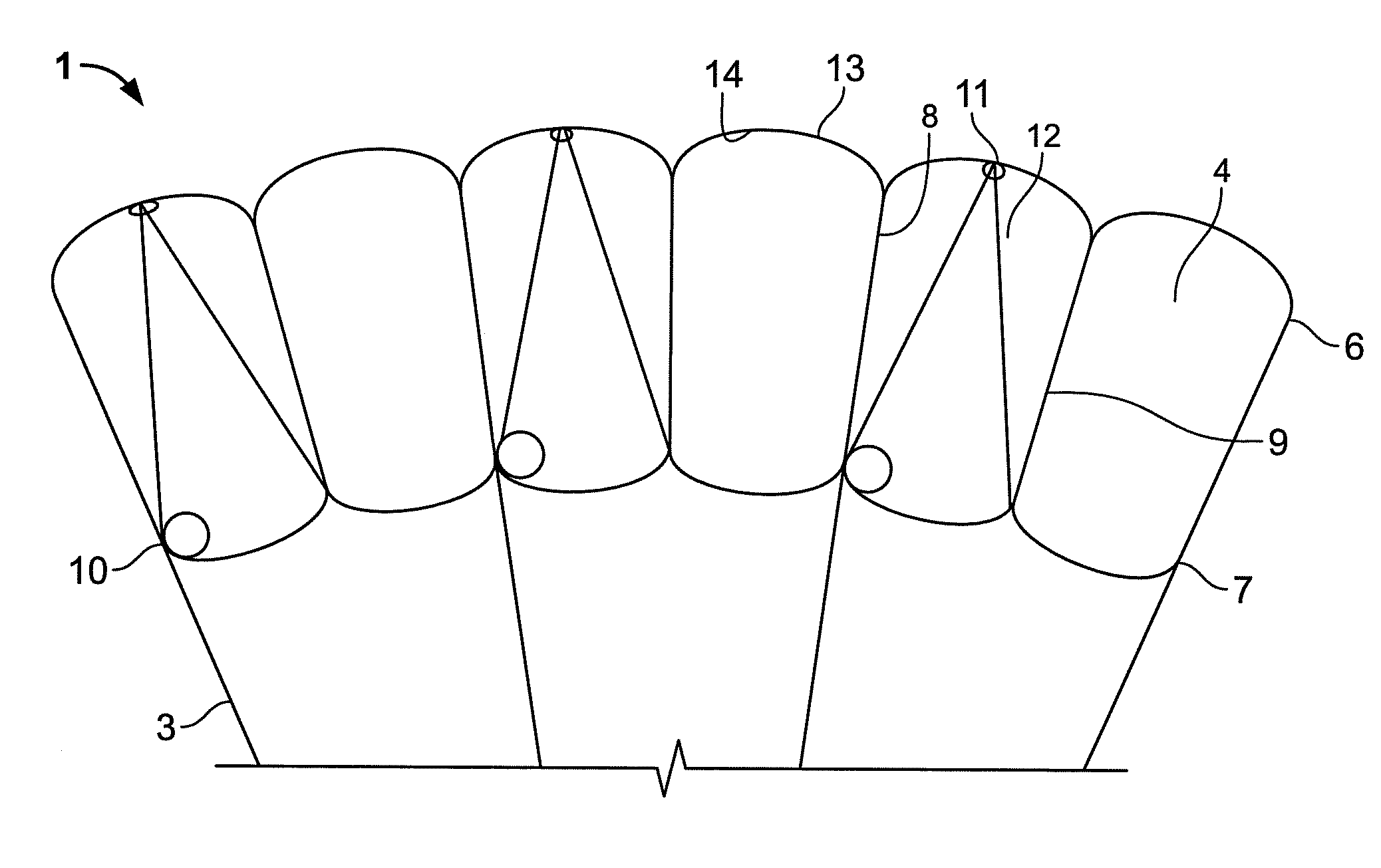
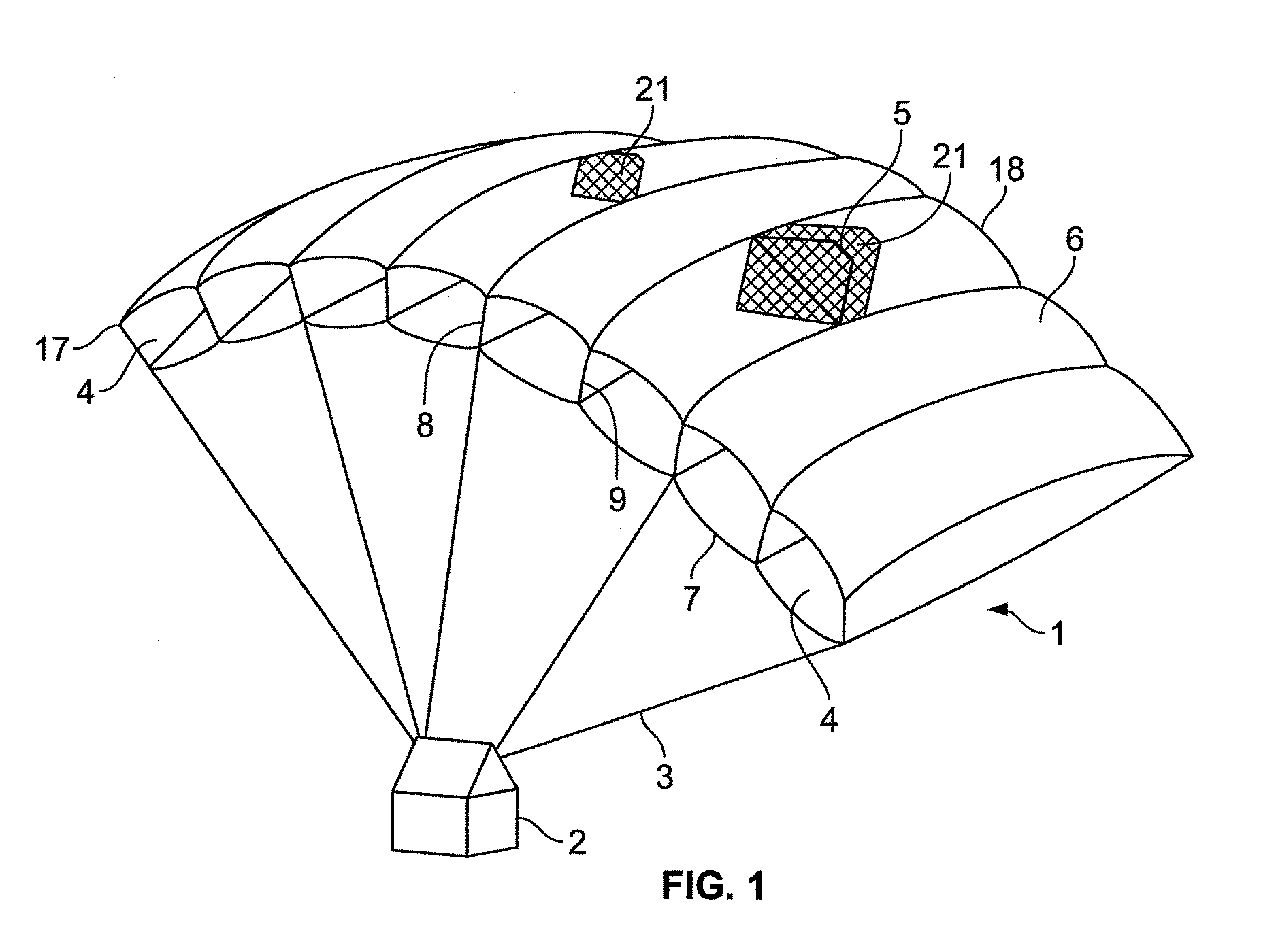
[0029]FIG. 1 is a schematic representation of an embodiment of the parafoil canopy 1 attached to payload rigging lines 3 which are further attached to a payload 2. The parafoil 1 is elliptical in planform and has a trailing edge 18 and a leading edge 17. The parafoil 1 has an upper surface canopy 6 and a lower surface canopy 7 attached to one another by structural cell walls 8 and non-structural cell walls 9 forming cells 4 within the parafoil 1. The structural cell walls 8 are attached to payload rigging lines 3. In the embodiment shown in FIG. 1, at least one cell 4 contains a vent 5 in the upper surface canopy 6, and each vent 5 is covered by a mesh member 21.

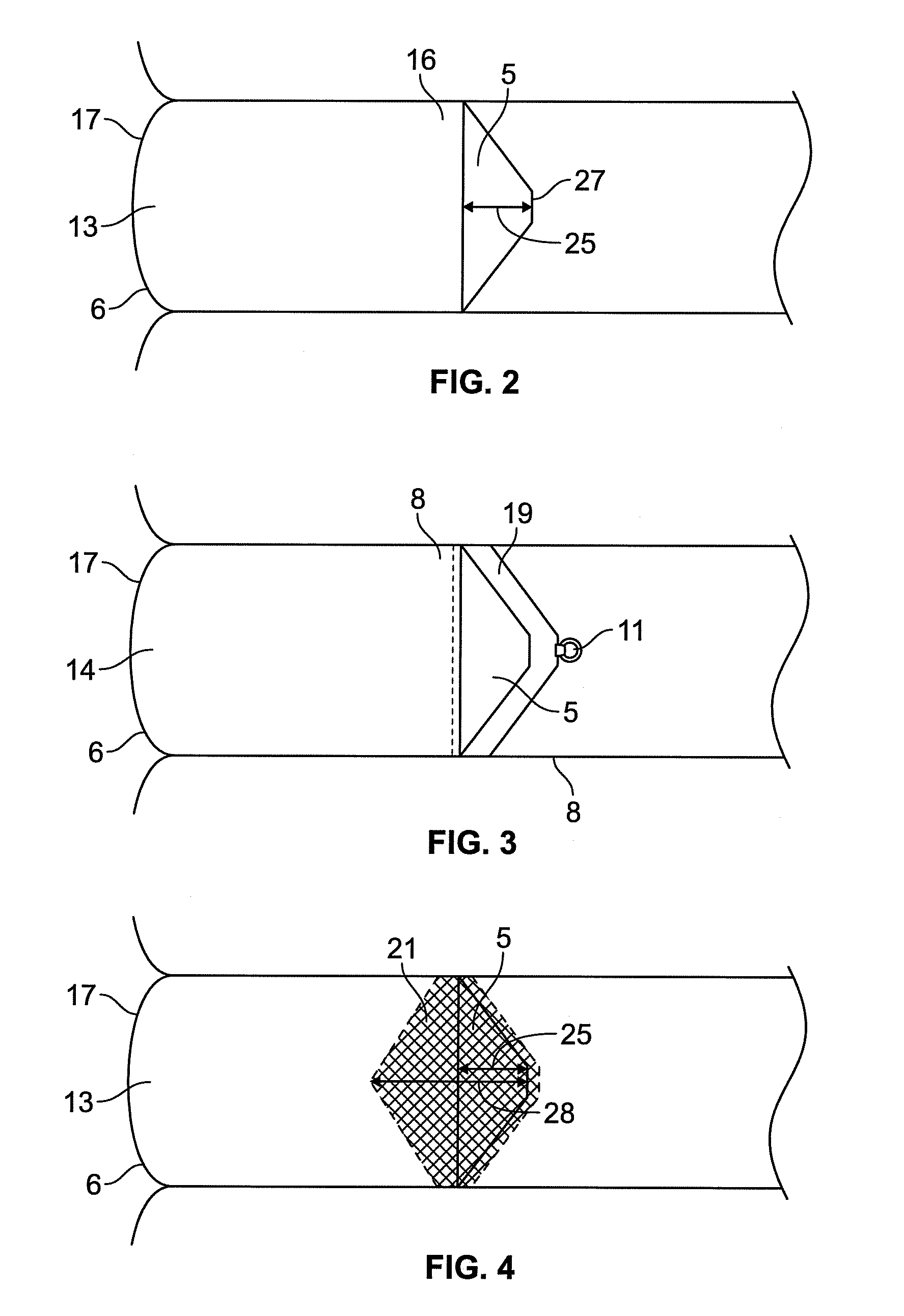
[0030]FIG. 2 is a schematic representation of an embodiment of top upper surface 13 of upper surface canopy 6 wherein the vent 5 is an isosceles trapezoid wherein the bases (26 and 27) are parallel and the longer base 26 is closest to the leading edge 17. The length 25 of vent 5 is the distance between the bases 26 and 27.

[0...


PUM


Abstract

A system is described to control the flight path of a parafoil. The physical control mechanism is a series of actuators embedded within the parafoil canopy that open a series of meshed venting systems in the upper surface of the parafoil canopy. Opening and closing the meshed venting system changes the forces and moments acting on the parafoil canopy in a consistent manner such that it can be used for flight control. The meshed venting system includes an internal sealing flap and a mesh member.

Description

CROSS-REFERENCE TO RELATED APPLICATION[0001]The present application is a continuation-in-part of U.S. Ser. No. 14 / 479,530 filed Sep. 8, 2014. The subject matter of that application is hereby incorporated by reference in its entirety.STATEMENT OF GOVERNMENT INTEREST[0002]The work that lead to certain aspects of this invention was supported in part by the U.S. Army Natick Soldier Research, Development and Engineering Center. Thus, the United States Government may have certain rights to this invention.FIELD OF THE INVENTION[0003]The present invention relates to a meshed venting system for a series of upper surface canopy spoilers within a parafoil of an aerial delivery system that are controlled by in-canopy actuators.BACKGROUND OF THE INVENTION[0004]Aerial payload delivery systems, also known as ram canopy parachute systems, offer the capability to deliver large payloads and or people to undeveloped or inaccessible locations. The canopies in these systems are well known and often refe...

Claims


Application Information

Patent Timeline
IPC IPC(8): B64D17/34B64D17/18B64D17/22B64D17/02
CPCB64D17/34B64D17/22B64D17/18B64D17/025B64D17/20
Inventor COSTELLO, MARK FWARD, MICHAEL BRIANSCHEUERMANN, EDWARD JAMESBERGERON, KEITHSHURTLIFF, MICHAEL WAYNENOETSCHER, GREGORY MICHAEL
Owner EARTHLY DYNAMICS LLC
Why Eureka
Try Eureka