Color filter substrate and manufacturing method thereof, organic electroluminescent display panel and display device

a technology substrate, which is applied in the direction of instruments, discharge tubes luminescnet screens, optical elements, etc., can solve the problems of low light output efficiency of organic electroluminescent display panel, poor display effect, etc., to achieve low light output efficiency and improve light output efficiency

Active Publication Date: 2017-02-21
BOE TECH GRP CO LTD
View PDF9 Cites 0 Cited by
  • Summary
  • Abstract
  • Description
  • Claims
  • Application Information

AI Technical Summary

Benefits of technology

[0006]The technical problem to be solved by the present invention is to provide a color filter substrate with improved light output efficiency and a manufacturing method thereof, an organic electroluminescent display panel and a display device, which can solve the problem that an existing organic electroluminescent display panel is low in light output efficiency.
[0008]The first adhesive layer of the color filter substrate of the present invention is provided with the scattering particles, which may scatter light coming from a display light source, so that the light is more divergent and softer and the uniformity of the light is improved. In addition, in the present invention, the two adjacent color filters are at least partially overlapped, and the overlapped part of the two color filters is also equivalent to a black matrix; meanwhile, each black matrix on the color filter substrate is at least partially arranged at the overlapped position of the two adjacent color filters, which is equivalent to increasing the thickness of the black matrixes on the color filter substrate; and it could be understood that, a color filter with a color (that is, corresponding to a sub-pixel) is arranged between two adjacent black matrixes, and under such a condition, because the thickness of the black matrixes is increased, the light corresponding to the sub-pixel may be effectively prevented from being scattered to a sub-pixel adjacent to the sub-pixel after being scattered by the scattering particles, and thus brightness loss is avoided.
[0015]The organic electroluminescent display panel including the color filter substrate has high light output efficiency and good display effect.
[0023]The display device in this embodiment has a good display effect as including the organic electroluminescent display panel.

Problems solved by technology

Due to the loss of energy in the luminescent process of the organic electroluminescent device, the light output efficiency of the organic electroluminescent device is low, then the light output efficiency of the organic electroluminescent display panel is low, and the display effect is poor.

Method used


Image

  • Color filter substrate and manufacturing method thereof, organic electroluminescent display panel and display device
  • Color filter substrate and manufacturing method thereof, organic electroluminescent display panel and display device
  • Color filter substrate and manufacturing method thereof, organic electroluminescent display panel and display device

Examples


embodiment 1

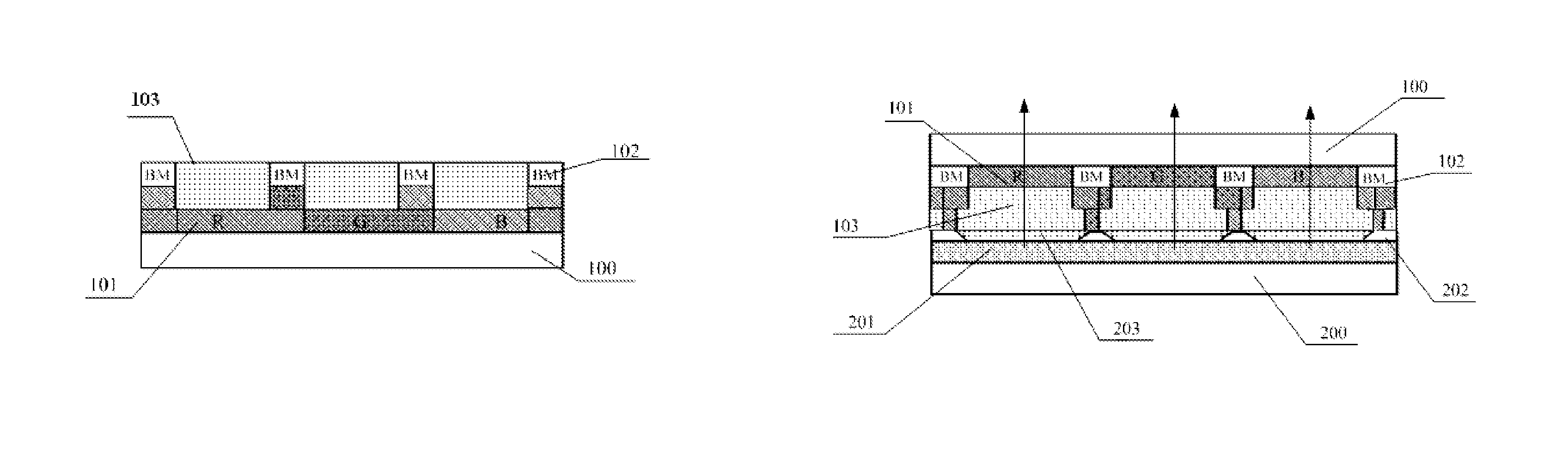
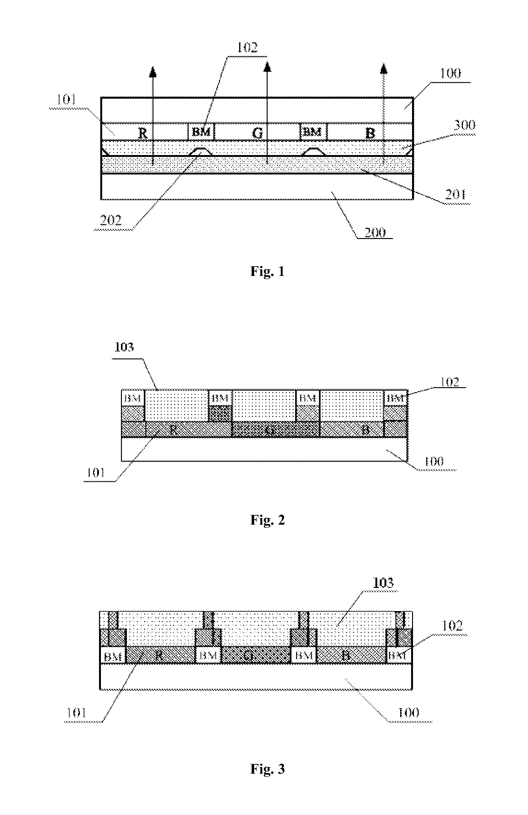
[0042]As shown in FIG. 2 and FIG. 3, this embodiment provides a color filter substrate, including a first base 100, and color filters 101 and black matrixes 102 arranged on the first base 100, wherein two adjacent color filters 101 are at least partially overlapped, and each black matrix 102 is at least partially arranged at the overlapped position of the two adjacent color filters 101, and the color filter substrate further includes a first adhesive layer 103 for eliminating section differences between the adjacent color filters 101 or between the color filters 101 and the black matrixes 102, and the first adhesive layer 103 is provided with scattering particles.

[0043]The first adhesive layer 103 of the color filter substrate in this embodiment is provided with the scattering particles, which may scatter light coming from a display light source, so that the light is more divergent and softer and the uniformity of the light is improved. In addition, in this embodiment, the two adjac...

embodiment 2

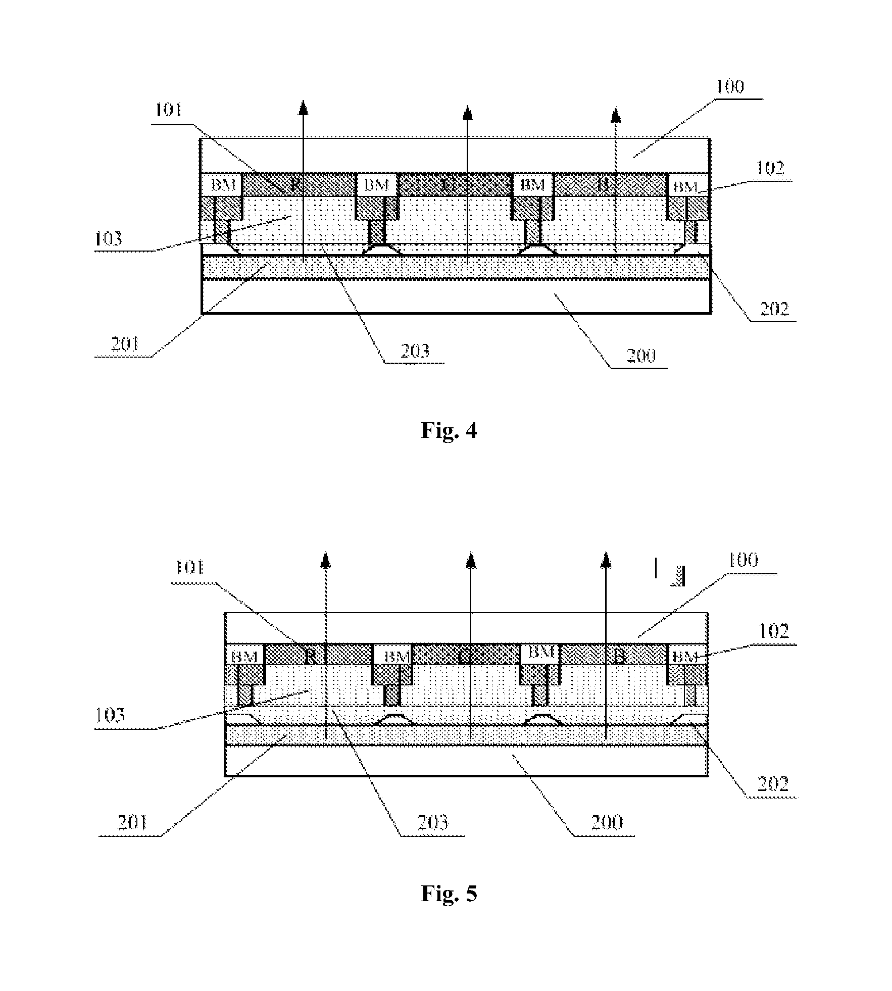
[0049]As shown in FIG. 4 and FIG. 5, this embodiment provides an organic electroluminescent display panel, including the color filter substrate in embodiment 1 and an array substrate which is cell-aligned with the color filter substrate.

[0050]In this embodiment, the organic electroluminescent display panel including the color filter substrate in embodiment 1 has high light output efficiency and ensures good uniformity of light.

[0051]Preferably, the array substrate includes a second base 200 and a plurality of pixel units arranged on the second base 200, wherein each pixel unit includes a plurality of organic electroluminescent devices, and the adjacent organic electroluminescent display devices are isolated from each other by a pixel defining layer 202, wherein the section difference of the pixel defining layer 202 is eliminated by a second adhesive layer 203. Because the section difference on the light output surface of the array substrate is eliminated by the second adhesive layer...

embodiment 3

[0057]This embodiment provides a display device, including the organic electroluminescent display panel in embodiment 2.

[0058]The display device may be any product or component with a display function, such as a mobile phone, a tablet computer, a television, a display, a notebook computer, a digital photo frame or a navigator.

[0059]The display device including the organic electroluminescent display panel in embodiment 2 has better performance and better display effect.

[0060]Of course, the display device of this embodiment may further include other conventional structures, such as a power unit and a display drive unit.


PUM

PropertyMeasurementUnit
coloraaaaaaaaaa
luminescentaaaaaaaaaa
energyaaaaaaaaaa

Abstract

The present invention provides a color filter substrate and a manufacturing method thereof, an organic electroluminescent display panel and a display device. The color filter substrate of the present invention comprises a first base, and a plurality of color filters and black matrixes arranged on the first base, wherein two adjacent color filters are at least partially overlapped, and each black matrix is at least partially arranged at the overlapped position of the two adjacent color filters; and the color filter substrate further comprises a first adhesive layer for eliminating section differences between the adjacent color filters or between the color filters and the black matrixes, and the first adhesive layer is provided with scattering particles therein. The color filter substrate can be used in the organic electroluminescent display panel.

Description

[0001]This is a National Phase Application filed under 35 U.S.C. §371 as a national stage of PCT / CN2014 / 087384, filed Sep. 25, 2014, an application claiming the benefit to Chinese Application No. 201410165881.2, filed Apr. 23, 2014; the content of each of which is hereby incorporated by reference in its entirety.FIELD OF THE INVENTION[0002]The present invention belongs to the field of organic electroluminescent display technology, and particularly relates to a color filter substrate and a manufacturing method thereof, an organic electroluminescent display panel and a display device.BACKGROUND OF THE INVENTION[0003]The basic structure of an organic electroluminescent device (e.g. OLED) includes an anode layer, a cathode layer and a “luminescent layer” sandwiched between the anode layer and the cathode layer, wherein the luminescent layer includes one or more organic layers. Under the action of an external voltage, electrons and holes are respectively injected into the organic layers ...

Claims


Application Information

Patent Timeline
Patent Type & Authority Patents(United States)
IPC IPC(8): H01J1/62H05B33/10H01L27/32H05B33/04G02B5/20G02F1/1335H01L21/77
CPCG02B5/201G02B5/20G02F1/1335H01L21/77H01L27/32H05B33/04H05B33/10H10K59/38H10K59/00H10K50/865
Inventor WU, CHANGYENWANG, JUNRANCAO, KUNWANG, DONGFANGYUAN, GUANGCAI
Owner BOE TECH GRP CO LTD
Why Eureka
Try Eureka