Anchoring structure with concave landing zone

a technology of anchoring structure and landing zone, which is applied in the field of anchoring structure with concave landing zone, can solve the problems of increasing achieve the effects of reducing the chance of paravalvular leakage, less and less invasive, and reducing the chance of suturing the valve around the annulus

Active Publication Date: 2017-02-28
MEDTRONIC PS MEDICAL
View PDF655 Cites 20 Cited by
  • Summary
  • Abstract
  • Description
  • Claims
  • Application Information

AI Technical Summary

Benefits of technology

[0017]The invention provides methods and systems for reducing paravalvular leakage around heart valves. As replacement valve procedures become less and less invasive, the opportunity for suturing the valves around the annulus is reduced. However, minimizing the number of sutures used to secure the replacement valve may increase the chance of paravalvular leakage (PVL), as well as the opportunities for valve migration and valve stability when placed in-vivo.
[0018]Leakage associated with a heart valve can be either paravalvular (around the valve) or central (through the valve). Examples of various heart valves include aortic valves, mitral valves, pulmonary valves, and tricuspid valves. Central leakage may be reduced by heart valve design. Paravalvular leakage, on the other hand, may be reduced by creating a seal between the replacement heart valve and the implant site to prevent blood from flowing around the replacement heart valve. It is important that the seal between the replacement heart valve and the implant site does not adversely affect the surrounding tissue. Furthermore, it is important that the seal does not affect the flow dynamics around the replacement heart valve. In the case of the aortic valve, it is also important that the seal does not obstruct coronary flow.
[0021]In another embodiment of the invention, a valve assembly that reduces paravalvular leakage is provided. The valve assembly includes a bioprosthetic tissue heart valve attached to an anchoring structure. The anchoring structure includes a body having a proximal or inlet end and a distal or outlet end. The inlet frame has a sinusoidal-shaped single or double rail construction and is commonly referred to as the inlet rim. The outlet frame has a sinusoidal-shaped single or double rail construction and is commonly referred to as the outlet rim. The sinusoidal-shaped double rail construction of the inlet rim is C-shaped in cross section and forms the concave landing zone of the invention. The C-shape in cross section construction provides a bioprosthetic valve that is self-seating and that requires minimal adjustment.
[0023]In yet another embodiment of the invention, the concave landing zone of the bioprosthetic heart valve assembly provides an effective seal between the bioprosthetic replacement heart valve and the implant site to prevent paravalvular leakage.
[0029]The invention provides a method of preventing paravalvular leakage. Using the single, double and / or triple rail flared designs described herein, paravalvular leakage may be reduced by ensuring the inflow rim is substantially pushed against the aorta, hence forming a tight seal. In one method of implantation, a self-expanding replacement valve may be deployed into position with a delivery member, thereby pushing the inflow rim against the aorta to create a seal around the valve. In other words, a self-expandable inflow rim comprising the replacement heart valve provides the radial force necessary to position the bioprosthetic heart valve in the annulus.

Problems solved by technology

However, minimizing the number of sutures used to secure the replacement valve may increase the chance of paravalvular leakage (PVL), as well as the opportunities for valve migration and valve stability when placed in-vivo.

Method used


Image

  • Anchoring structure with concave landing zone
  • Anchoring structure with concave landing zone
  • Anchoring structure with concave landing zone

Examples


Embodiment Construction

[0047]While this invention may be embodied in many different forms, there are described in detail herein various embodiments of the invention. This description is an exemplification of the principles of the invention and is not intended to limit the invention to the particular embodiments illustrated.

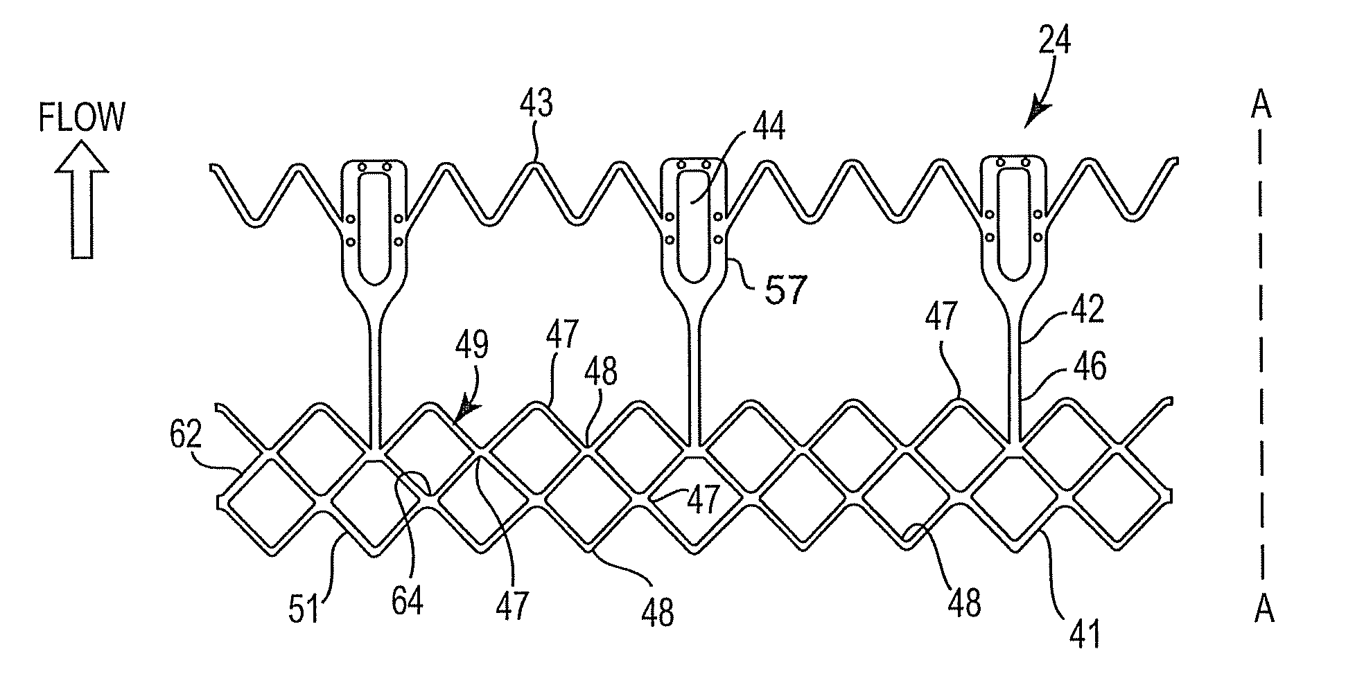
[0048]For the sake of consistency, the terms “peak” and “trough” are defined with respect to the proximal and distal ends of the anchoring structure in accordance with the invention. As seen in the Figures, each of the tubular anchoring structures has an inflow end, referred to herein as an inflow rim, and an outflow end, referred to herein as an outflow rim. With respect to the inflow and outflow rims “peaks” are concave relative to the proximal end of the anchoring structure and convex relative to the distal end of the anchoring structure. Troughs, on the other hand, are convex relative to the proximal end of the anchoring structure and concave relative to the distal end of the anchor...


PUM


Abstract

A method and device for reducing paravalvular leakage upon implantation of a replacement heart valve is provided. The valve assembly includes a tissue or bioprosthetic heart valve attached to an anchoring structure. The anchoring structure includes an inlet rim that is substantially C-shaped in cross section to form a concave landing zone. The anchoring structure self-seats when implanted in the sinus of a patient with the proximal and distal ends of the C-shaped inlet rim pushed against the aorta to effectively prevent paravalvular leakage.

Description

[0001]This application is a continuation in part of co-pending U.S. application Ser. No. 11 / 489,663 filed on Jul. 17, 2006, which is a continuation-in-part of application Ser. No. 10 / 680,071 filed on Oct. 6, 2003, now U.S. Pat. No. 7,101,396; and also claims priority to U.S. provisional application Ser. No. 61 / 184,650 filed on Jun. 5, 2009, the entireties of which are hereby incorporated by reference.BACKGROUND OF THE INVENTION[0002]1. Field of the Invention[0003]The invention relates to an anchoring structure for use in minimally invasive bioprosthetic heart valve replacement systems. More particularly, the invention relates to a tubular anchoring structure with an inflow end that includes a concave landing zone that reduces paravalvular leakage.[0004]2. Description of the Related Art[0005]The transport of vital fluids in the human body is largely regulated by valves. Physiological valves are designed to prevent the backflow of bodily fluids, such as blood, lymph, urine, bile, etc....

Claims


Application Information

Patent Timeline
Patent Type & Authority Patents(United States)
IPC IPC(8): A61F2/24
CPCA61F2/2418A61F2220/0016A61F2230/00A61F2230/0013A61F2230/0054A61F2230/0065
Inventor ELIZONDO, DAVIDMALEWICZ, ANDRZEJ M.WESTON, MATTHEW W.MYERS, KEITH E.
Owner MEDTRONIC PS MEDICAL
Why Eureka
Try Eureka