Fluidised bed pyrolysis apparatus and method

a technology of pyrolysis apparatus and flue gas, which is applied in the direction of lighting and heating apparatus, combustible gas purification/modification, and combustion types, etc., can solve the problem of done at the expense of char loss

Active Publication Date: 2017-02-28
UNIV OF PRETORIA +1
View PDF7 Cites 1 Cited by
  • Summary
  • Abstract
  • Description
  • Claims
  • Application Information

AI Technical Summary

Benefits of technology

[0021]Air may enter downwards or upwards through the nozzles into the fluidised beds. Horizontal jets may prevent sand from flowing into an air supply line. The recycle gas duct or line may enter as close as possible to the nozzle, where it mixes with cold air, and combusts in the fluidised bed.
[0027]The use of catalyst in the pyrolysis zone may allow more throughput of bio-mass because more CO2 is produced and therefore the reaction will be less endothermic.
[0033]Air supply to the fluidized bed may be preheated by exchanging heat from the gases exiting the combustion zone. This may substantially reduce the fluidized bed area required in the combustion zone to heat a given mass flow rate of hot particles. It also may reduce the amount of carbon that is combusted to form CO2, making the process more environmentally friendly.
[0034]The temperature of the combustion fluidized bed may be controlled by varying the rate of transfer of hot particles from the pyrolysis zone to the combustion zone, for example, by varying the speed of a motor driving the positive displacement apparatus such as a screw feeder used for the purpose.

Problems solved by technology

In order to reduce the electrical energy demand, char produced by the pyrolysis of the bio-mass is recycled as a fuel to the pyrolysis reaction where it is combusted to provide some of the energy required to maintain the pyrolysis temperature, however, this is done at the expense of the char being lost.

Method used


Image

  • Fluidised bed pyrolysis apparatus and method
  • Fluidised bed pyrolysis apparatus and method
  • Fluidised bed pyrolysis apparatus and method

Examples


Embodiment Construction

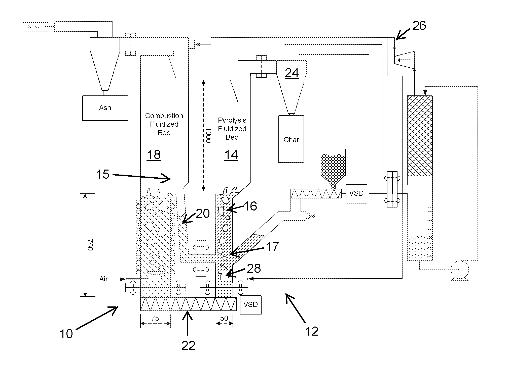
[0044]In the flow sheet 10 of FIG. 1, representing an embodiment of this invention, a pyrolysis apparatus 12 and a pyrolysis process is provided for rapidly heating bio-mass to be pyrolysed to bio-oil by mixing it in a pyrolysis fluidised bed 14 with hot particles, in the form of hot sand 16, from a separate fluidised bed operating in combustion conditions.

[0045]The combustion fluidised bed 18 has a cross sectional area 3 to 4 times that of the cross sectional area of the pyrolysis fluidised bed 14.

[0046]In FIG. 1, the combustion fluidised bed 18 is kept hot, typically around 900° C., by burning combustible gas and char. The hot sand 16 moves from the combustion region 15 to the pyrolysis region 17 by means of an “L” valve 20 which is known in fluidised bed technology.

[0047]The pyrolysis reaction cools the sand down to 500-600° C., and the cooled sand is returned by a screw conveyor 22 to the hot combustion fluidised bed 18 for re-heating.

[0048]Some char is entrained with the sand a...


PUM

PropertyMeasurementUnit
temperatureaaaaaaaaaa

Abstract

A carbonaceous feed pyrolysis apparatus is provided including two or more hot particle fluidized beds, and one or more positive displacement apparatus for the transfer of hot particles between two or more of the beds, wherein one or more of the fluidized beds contains a combustion zone. A bio-oil production process is also provided, including pyrolysis of a carbonaceous bio-mass using two or more fluidized beds, including a first combustion zone carried out in one or more combustion fluidized beds in which a particulate material is fluidized and heated, and a second pyrolysis zone carried out in one or more pyrolysis fluidized beds in which the hot particles heated in the combustion zone are used for pyrolysis of the bio-mass.

Description

INCORPORATION BY REFERENCE TO RELATED APPLICATIONS[0001]Any and all priority claims identified in the Application Data Sheet, or any correction thereto, are hereby incorporated by reference under 37 CFR 1.57. This application is the national phase under 35 U.S.C. §371 of prior PCT International Application No. PCT / ZA2011 / 000067 which has an International filing date of Sep. 8, 2011, which designates the United States of America, and which claims the benefit of U.S. Provisional Patent Application No. 61 / 381,917 filed Sep. 10, 2010, the disclosures of which are hereby expressly incorporated by reference in their entirety and are hereby expressly made a portion of this application.FIELD OF THE INVENTION[0002]The invention relates to the pyrolysis of carbonaceous material, such as bio-mass, in a fluidised bed pyrolysis apparatus.BACKGROUND TO THE INVENTION[0003]Fast pyrolysis of bio-mass involves rapidly heating solid bio-mass to a temperature of 400° C. to 600° C. in reducing condition...

Claims


Application Information

Patent Timeline
Patent Type & Authority Patents(United States)
IPC IPC(8): C10B49/22F23C10/00C10K1/16C10B53/02F23C10/24F23C10/20F23C10/01
CPCC10B49/22C10B53/02C10K1/16F23C10/005F23C10/01F23C10/20F23C10/24Y02E50/14Y02P20/145Y02P20/129Y02E50/10
Inventor HEYDENRYCH, MICHAEL DAVIDSWART, STEPHEN DAVIDBOATENG, AKWASI ACHEAMPONG
Owner UNIV OF PRETORIA
Why Eureka
Try Eureka