Optical image capturing system
a technology of optical image and capturing system, which is applied in the field of optical image capturing system, can solve the problems of image formation distortion rate, difficulty in manufacturing, deterioration of quality, etc., and achieve the effects of fine tuning, reducing the height of the optical system, and improving the ability of aberration correction
- Summary
- Abstract
- Description
- Claims
- Application Information
AI Technical Summary
Benefits of technology
Problems solved by technology
Method used
Image

Examples
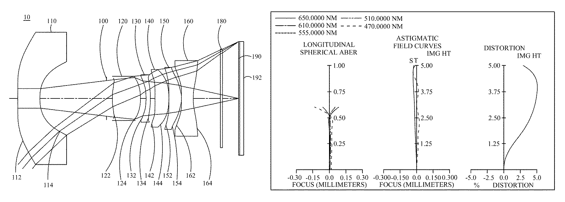
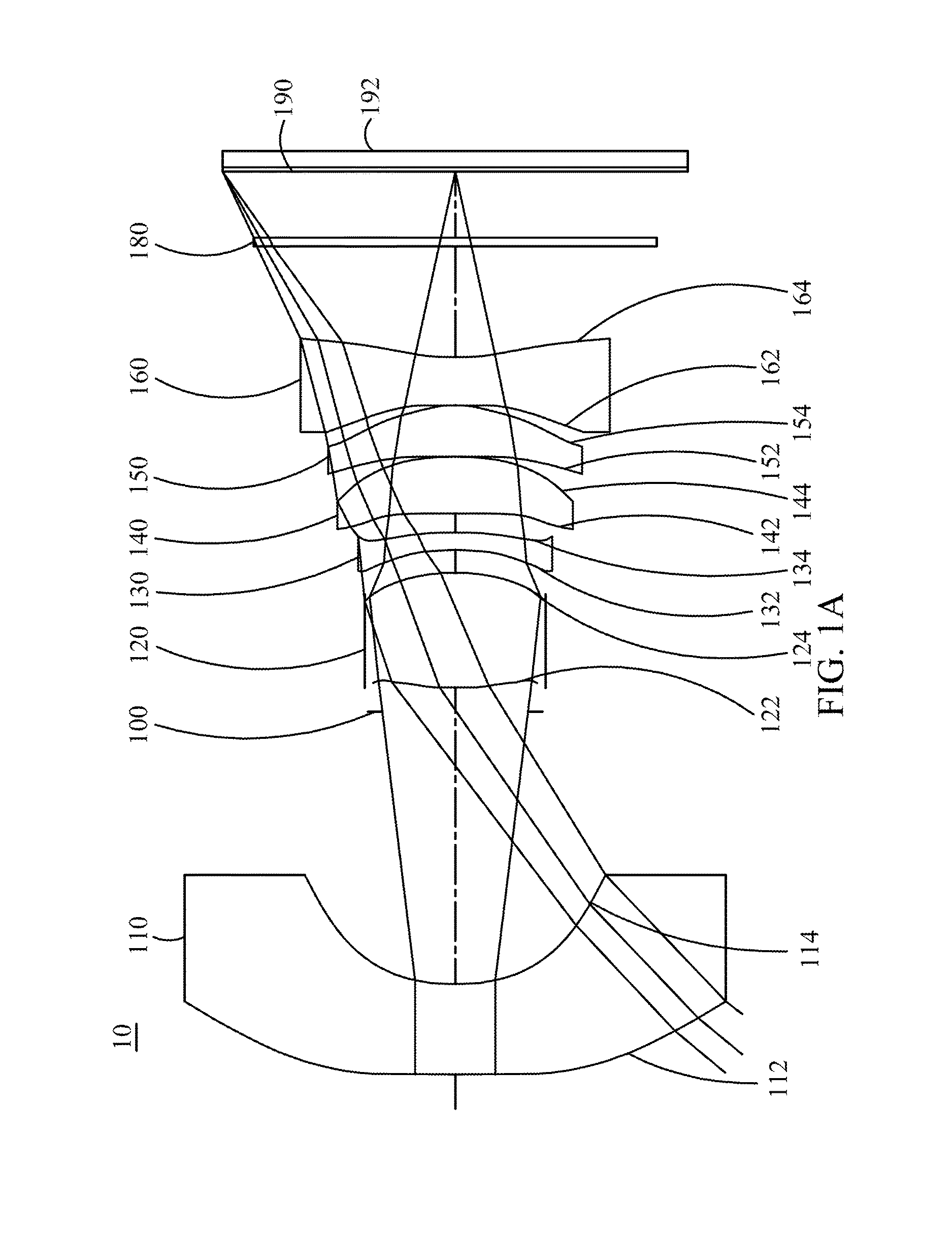
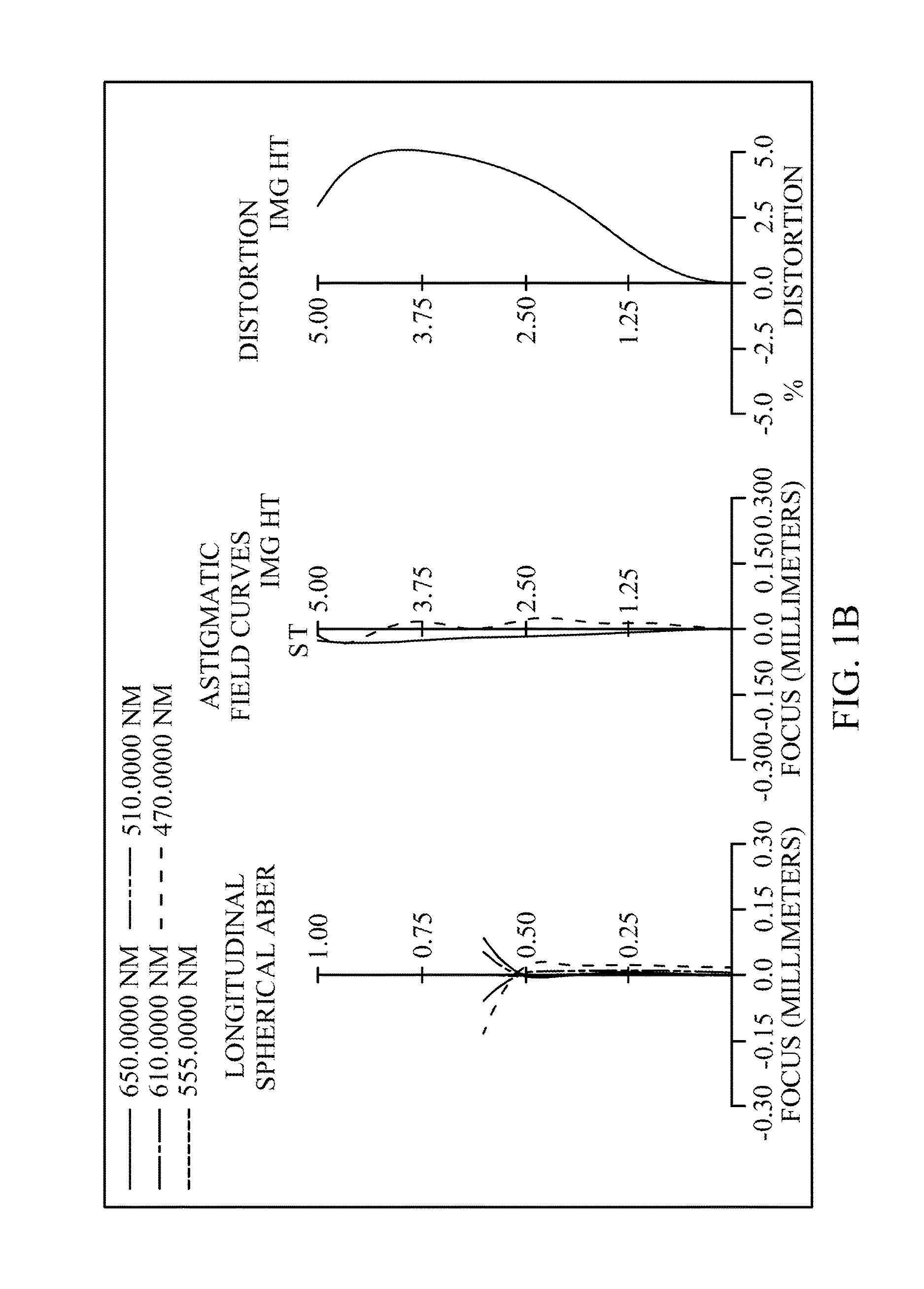
first embodiment
[0142]In the first embodiment, a horizontal distance in parallel with the optical axis from a coordinate point on the object-side surface of the first lens element at height ½ HEP to the image plane is ETL. A horizontal distance in parallel with the optical axis from a coordinate point on the object-side surface of the first lens element at height ½ HEP to a coordinate point on the image-side surface of the sixth lens element at height ½ HEP is EIN. The following relations are satisfied; ETL=19.304 mm, EIN=15.733 mm and EIN / ETL=0.815.
[0143]The first embodiment satisfies the following relations: ETP1=2.371 mm, ETP2=2.134 mm, ETP3=0.497 mm, ETP4=1.111 mm, ETP5=1.783 mm and ETP6=1.404 mm. A sum of ETP1 to ETP6 described above SETP=9.300 mm. TP1=2.064 mm, TP2=2.500 mm, TP3=0.380 mm, TP4=1.186 mm, TP5=2.184 mm and TP6=1.105 mm. A sum of TP1 to TP6 described above STP=9.419 mm. SETP / STP=0.987. SETP / EIN=0.5911.
[0144]The present embodiment particularly controls the ratio relation (ETP / TP) o...
second embodiment
[0188]In the optical image capturing system of the second embodiment, a sum of focal lengths of all lens elements with positive refractive power is ΣPP. The following relations are satisfied: ΣPP=21.726 mm and f3 / ΣPP=0.321. Hereby, it is favorable for allocating the positive refractive power of a single lens element to other positive lens elements and the significant aberrations generated in the process of moving the incident light can be suppressed.
[0189]In the optical image capturing system of the second embodiment, a sum of focal lengths of all lens elements with negative refractive power is ΣNP. The following relation is satisfied: ΣNP=−22.398 mm and f1 / ΣNP=0.533. Hereby, it is favorable for allocating the negative refractive power of a single lens element to other negative lens elements.
[0190]Please refer to the following Table 3 and Table 4.
The detailed data of the optical image capturing system of the second embodiment is as shown in Table 3.
[0191]
TABLE 3Data of the optical i...
third embodiment
[0205]In the optical image capturing system of the third embodiment, a sum of focal lengths of all lens elements with positive refractive, power is ΣPP. The following relation is satisfied: ΣPP=23.704 mm and f3 / ΣPP=0.374. Hereby, it is favorable for allocating the positive refractive power of a single lens element to other positive lens elements and the significant aberrations generated in the process of moving the incident light can be suppressed.
[0206]In the optical image capturing system of the third embodiment, a sum of focal lengths of all lens elements with negative refractive power is ΣNP. The following relation is satisfied: ΣNP=−24.917 mm and f1 / ΣNP=0.483. Hereby, it is favorable for allocating the negative refractive power of a single lens element to other negative lens elements.
[0207]Please refer to the following Table 5 and Table 6.
The detailed data of the optical image capturing system of the third embodiment is as shown in Table 5.
[0208]
TABLE 5Data of the optical image...
PUM
 Abstract
Description
Claims
Application Information
 - R&D
- Intellectual Property
- Life Sciences
- Materials
- Tech Scout
- Unparalleled Data Quality
- Higher Quality Content
- 60% Fewer Hallucinations
Browse by: Latest US Patents, China's latest patents, Technical Efficacy Thesaurus, Application Domain, Technology Topic, Popular Technical Reports.
© 2025 PatSnap. All rights reserved.Legal|Privacy policy|Modern Slavery Act Transparency Statement|Sitemap|About US| Contact US: help@patsnap.com