Methods and systems for generating and using simulated 3D images

a technology of 3d images and systems, applied in the field of projection apparatuses, can solve the problems of destroying the “holographic” effect of virtual images, affecting the fidelity of the combined 3d image, and not being practical for use in well-lit areas, so as to improve the perceived image parallax and foreground image fidelity, improve the overall effect, and enhance the

Active Publication Date: 2017-02-28
ARHT MEDIA
View PDF23 Cites 14 Cited by
  • Summary
  • Abstract
  • Description
  • Claims
  • Application Information

AI Technical Summary

Benefits of technology

[0072]However, these shortcomings can be overcome or ameliorated by controlling the opacity and luminance levels of the front display device, and/or by using techniques such as providing “traveling mattes” on the rear screen. To be more specific, adjusting the opacity and luminance values of the background display or the front display, with respect to each other, can improve the perceived image parallax and the foreground image fidelity, of the system. In that regard, it is typically preferred, but not essential, that the background opacity should be adjusted to between 20% and 40% of the foreground layer so as to achieve a well perceived three dimensional effect.
[0073]The use of traveling mattes may be achieved physically, but in most cases, is done by editing the image content using a computer application. Essentially, a traveling matte is an artificial black mask th

Problems solved by technology

This is because if the viewer were to see the background image through the front image, it would destroy the “holographic” effect of the virtual image.
A common problem with this approach is that the light from the background panel is used to provide the lighting effect on the front panel.
As such, with normal background panels and projection apparatuses, the combined 3D image is dark and/or dull, and is typically only useful in darkened display areas.
While this is acceptable in some display areas, it is not practical for use in well-lit areas, such as in outdoor displays, or displays in a mall setting.
However, these boxes require a relatively large profile, which increases the overall size of the screen, and thereby, limit th

Method used


Image

  • Methods and systems for generating and using simulated 3D images
  • Methods and systems for generating and using simulated 3D images
  • Methods and systems for generating and using simulated 3D images

Examples


case 32

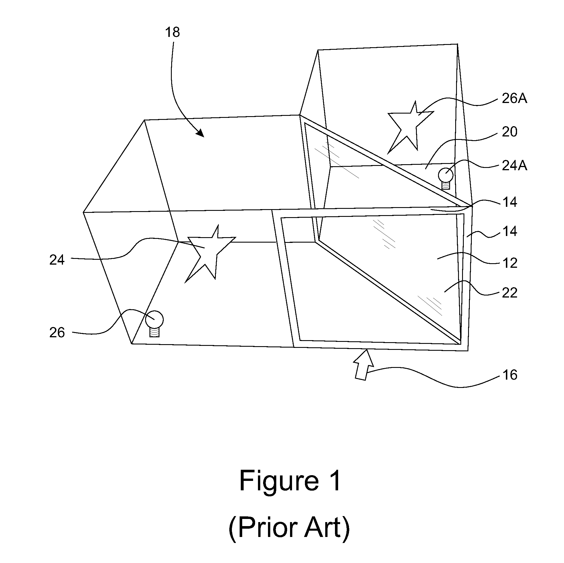
[0134]Case 32 can have any suitable width, height or depth, as required for the environment where apparatus 30 is used. By way of example, for a display item, case 32 could have a width of 2 meters, a height of 1.5 meters, and a depth of 1 meter. Obviously, the height, width and depth relationships can be modified as required or as needed.

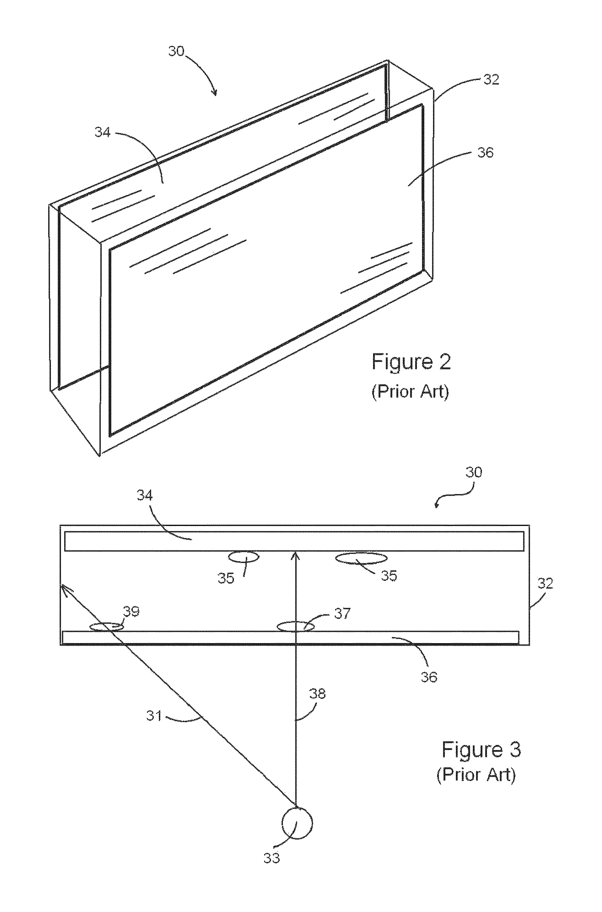
[0135]As best seen in FIG. 3, when viewed in the direction shown by arrow 38, a viewer 33 will see the image, which is represented by reference numeral 37, shown on front display 36, against an image represented by reference numerals 35 on the background display 34, when the viewer 33 views the images from directly in front of case 32.

[0136]As such, the two program material images are interrelated. The programming and the nature of the computers employed to interrelate the images, and their synchronization, are beyond the scope of the present invention. Similarly, the brightness and luminosity of the images on the front display 36 and / or background...


PUM


Abstract

A three-dimensional image simulation device for managing a live event comprising an image capturing device for capturing live captured data corresponding to a presenter and generating, in real-time, hologram data based on the live captured data. An output interface for broadcasting the hologram data in real-time to at least one additional location containing an audience, wherein the hologram data is used to create a hologram of the presenter at the at least one additional location based on an apparent parallax effect in a simulated three-dimensional display device, the hologram creating a three-dimensional illusion for the audience regarding actual presence of the presenter at the at least one additional location. Furthermore, an input interface for receiving audience data from the at least one additional location regarding interaction between the hologram and the audience and a display device for displaying images based on audience data to the presenter.

Description

PRIORITY[0001]This application claims the benefit of priority from U.S. Provisional Application No. 62 / 258,172, filed Nov. 10, 2015, entitled “Methods and Systems for Generating and Using Simulated 3D Images,” which is hereby incorporated herein by reference in its entirety.TECHNICAL FIELD[0002]This invention relates to projection apparatus, and in particular the invention relates to a projection apparatus which is portable and scalable, and which is used in a manner so that a viewer will see a video presentation which comprises a simulated three dimensional (3D) image comprising a virtual image which is seen against a background wherein the background may contain a further image which varies in a programmed manner in keeping with the actions being portrayed by the virtual image.[0003]This invention also relates to a low profile, simulated three dimensional (3D) display device having improved picture quality and appearance, and which is both portable and scalable. The display device...

Claims


Application Information

Patent Timeline
IPC IPC(8): G03H1/00G03H1/08H04N7/18G03H1/26H04N13/363H04N13/395
CPCG03H1/0005H04N7/183G03H1/0891G03H1/26G03H2001/0088H04N21/816H04N13/395H04N13/366G06Q30/0269G02B30/56H04N13/363G03H1/08G03H1/2249G03H2001/0061G03H2001/2284G03H2210/62G03H2226/02G03H2226/04G03H2226/05
Inventor DUFFY, JOHN PAUL
Owner ARHT MEDIA
Why Eureka
Try Eureka