Method and apparatus to effectively reduce a non-active detection gap of an optical sensor

a technology of optical sensors and non-active gaps, applied in the field of optical sensors, can solve the problems of non-active gaps between color sensors, presenting time and space differences in real terms for red, green and blue color information, dynamically active objects moving at variable rates, etc., and achieves the effect of reducing the distance between corresponding elements, enhancing the optical congruence of the first linear array, and effective reducing non-active gaps

Active Publication Date: 2007-11-20
LYNX SYST DEVERS
View PDF14 Cites 4 Cited by
  • Summary
  • Abstract
  • Description
  • Claims
  • Application Information

AI Technical Summary

Benefits of technology

[0009]This invention effectively reduces the non-active gap between sensor elements and thus reduces the time delay between such sensor elements in receiving image information, such as for example, the red, green and blue image components of a moving subject. The image fidelity is therefore improved because the combined image components present a closer match to the true image at an instantaneous moment or “snapshot” of interest. In other words, optical congruence may be enhanced by the use of the invention.
[0010]One implementation includes an optical sensor apparatus for effectively reducing a non-active gap. The optical sensor may have a first linear array of sensor segments and a second linear array of sensor segments separated by a first non-active gap having a first width. A first optical fiber has a first end oriented toward a field of view and a second end oriented toward a sensor segment of the first linear array of sensor segments. A second optical fiber has a first end oriented toward the field of view and located a first distance, less than the first width, from the first end of the first optical fiber and a second end oriented toward a sensor segment of the second linear array of sensor segments. This effectively reduces the distance between corresponding elements of the first and second linear arrays and therefore enhances the optical congruence of the first linear array in relation to the second linear array.
[0013]The separation of the second ends of the optical fibers may involve at least one spacer for proper positioning. The apparatus for effectively reducing a non-active gap of an optical sensor may have a first optical fiber and a second optical fiber are mounted such that a first end of the each optical fiber is oriented toward the field of view and the second end is directed towards a sensor. A first spacer is mounted between the second end of the first optical fiber and the second end of the second optical fiber to locate the second ends further apart than the first ends so as to correspond to elements of an optical sensor.
[0014]The invention also provides a method of effectively reducing a non-active gap of an optical sensor. The optical sensor has a first linear sensor element and a second linear sensor element separated by a first non-active gap having a first width and a third linear sensor element separated from the second linear sensor element by a second non-active gap of a second width. A first end of each optical fiber is oriented toward the field of view and the second end of each optical fiber is oriented toward the first, second and third linear sensor elements, respectively. The first end of a second optical fiber is located a first distance, less than the first width, from the first end of the first optical fiber and the first end of a third optical fiber is located a third distance, less than the second width, from the first end of the second optical fiber. Using this method, the optical congruence of said linear sensors may be enhanced in relation to each other.
[0015]The apparatus effectively reduces a non-active gap of an optical sensor or sensors. The apparatus gathers light information at or near a field of view and directs the image information to at least two linear sensor elements of an optical sensor so as to improve the image fidelity of the subject by enhancing the optical congruence capability of the optical sensor at an instantaneous or “photographic” time of interest.

Problems solved by technology

Dynamically active objects moving at variable rates pose a difficulty in high fidelity color imaging, particularly when a large depth-of-field is required.
In such a case, the separation of sensor elements results in an inaccurate representation of the events as the contestants cross the finish line.
The non-active gap between color sensors therefore presents a time and space difference in real terms for red, green and blue color information intended to be recorded simultaneously.
It may not be possible to accurately interpolate such information in the combined red, green and blue color image.
This can cause an image to be blurred substantially, to the point where loss of image fidelity is responsible for the inability to determine the outcome of a competition, or even to determine the distinguishing characteristics of competitors.

Method used


Image

  • Method and apparatus to effectively reduce a non-active detection gap of an optical sensor
  • Method and apparatus to effectively reduce a non-active detection gap of an optical sensor
  • Method and apparatus to effectively reduce a non-active detection gap of an optical sensor

Examples


Embodiment Construction

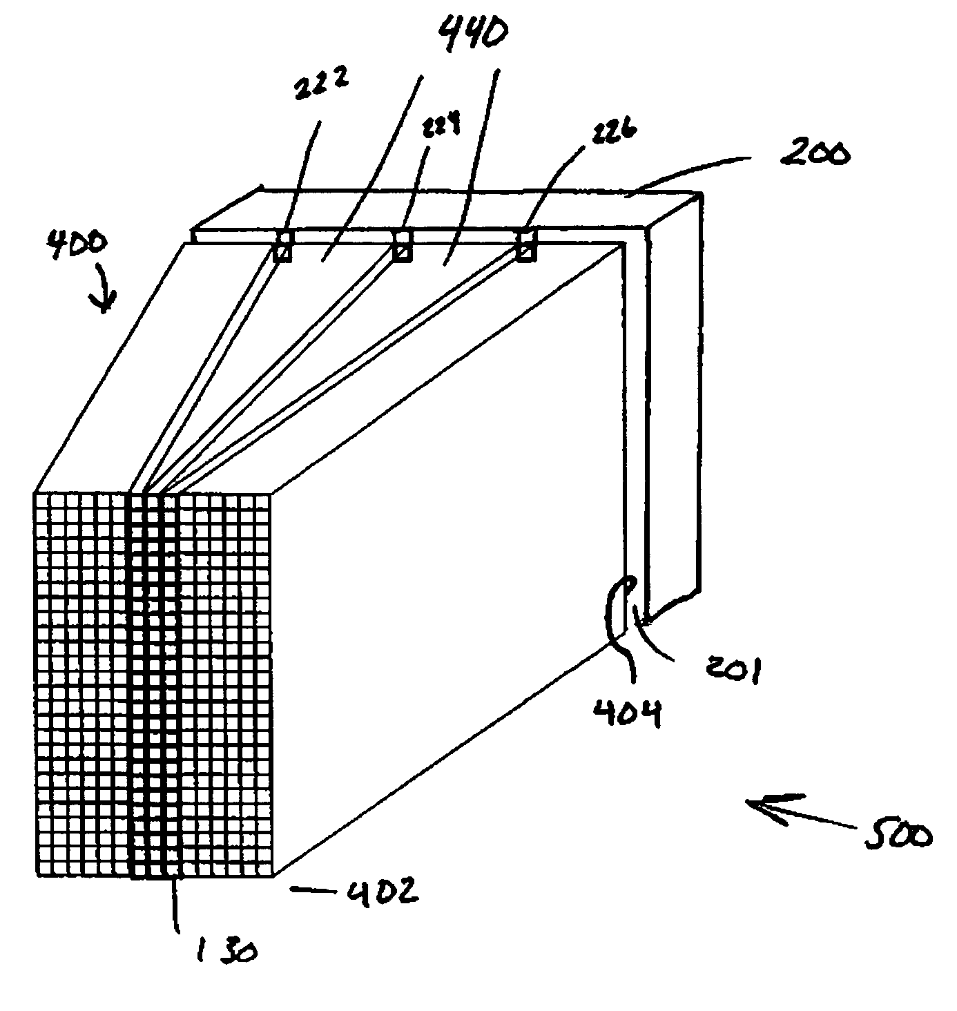
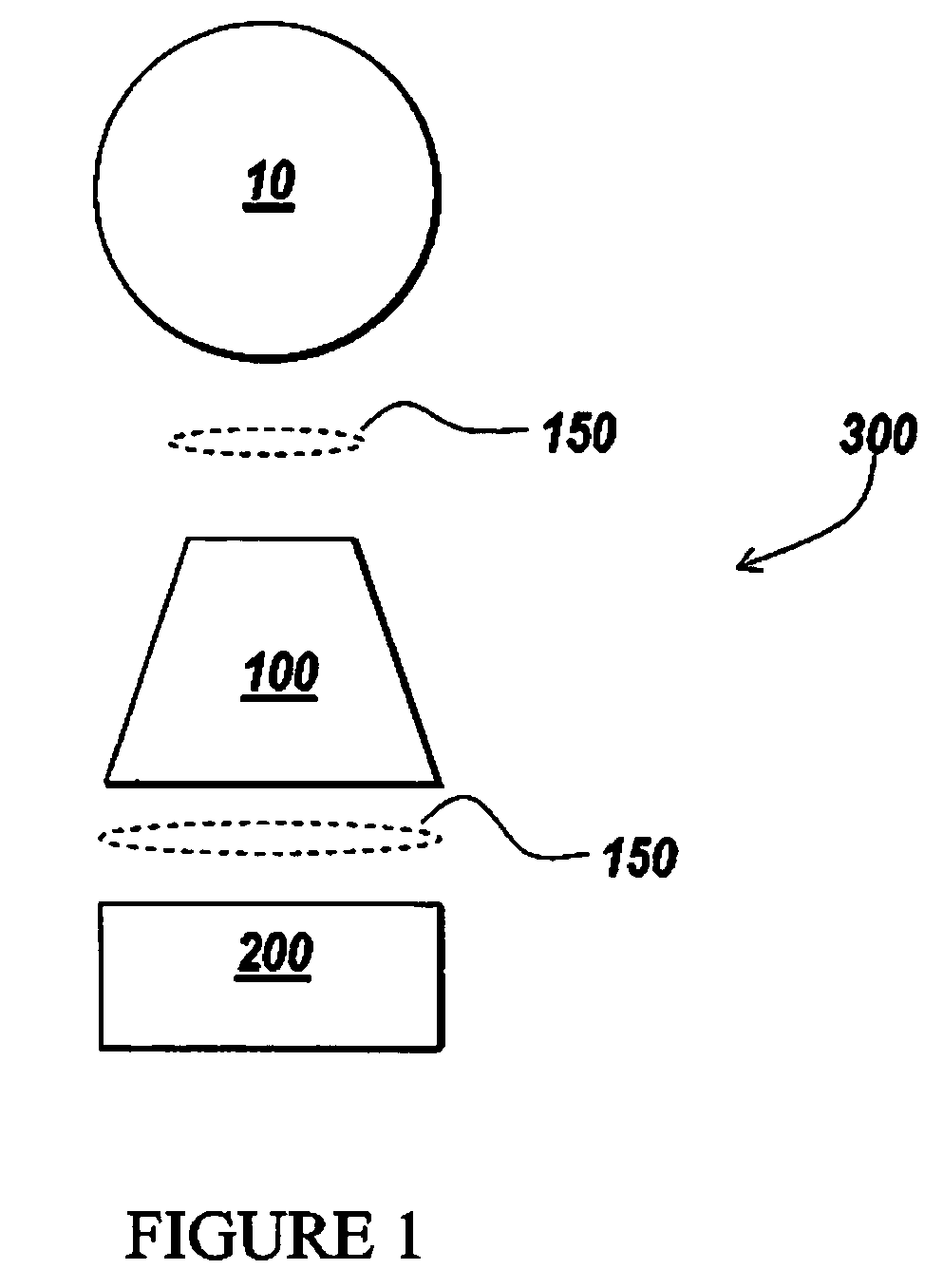
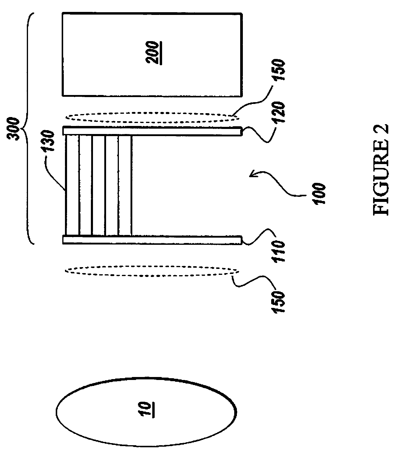
[0024]The invention addresses the difficulties of the prior art by the use of optical fibers oriented to obtain visual images from a field of view and distribute components of the optical images to more widely-spaced sensor elements of one or more optical sensors. This can enhance the optical congruence of the image obtained through the more widely-spaced sensor elements and eliminate inaccuracies caused by non-active optical gaps in the sensors. The image fidelity of a subject can be improved at an instantaneous or “photographic” time of interest by reducing the potential image degrading effects between the sensor elements. Such image degrading effects can include a differential time delay, angular and / or positional differences between the sensor elements. Specifically, optical congruence is enhanced in that the image information received by each sensor element at any instantaneous time is a closer representation of the original subject field than it would be if the sensor elements...


PUM


Abstract

An apparatus is provided to effectively reduce the non-active detection gap between sensor elements of an optical sensor. Reducing the non-active gap can subsequently reduce the time delay between sensor elements, mitigating the image degrading effects of a composite element time delay. While applicable to use with a wide range of optical sensors, the invention may be used for detecting aspects of a variable-rate dynamic colorful object using a matrix sensor or a tri-linear color CCD sensor. In one variation, optical fibers extend from a first fiber optic faceplate to a second fiber optic faceplate. The optical fibers can be oriented toward or directly mounted to the sensor elements. A spacer may be used to separate the optical fibers for alignment with the sensor elements and the other end of the optical fibers are attached to each other.

Description

FIELD OF THE INVENTION[0001]This invention relates to optical sensors and more specifically relates to methods and apparatus for redirecting light in order to effectively reduce a non-active detection gap between optical sensor elements of one or more optical sensors.BACKGROUND OF THE INVENTION[0002]Optical sensors are used for a wide variety of imaging purposes. An optical sensor, such as a linear sensor, may have multiple sensor elements, each of which captures a portion of the light information of an object or scene of interest. The manufacture of optical sensors may require a non-active gap between these sensor elements. The non-active gap is a portion of the optical sensor that can not detect an optical signal. In one example, linear arrays of distinct red, green and blue light capturing sensor elements are separated by a linear area, the non-active gap, where the combined sensor is not capable of capturing an optical signal.[0003]Similarly, optical sensors with one optical sen...

Claims


Application Information

Patent Timeline
Patent Type & Authority Patents(United States)
IPC IPC(8): G01J1/04G02B6/00G02B6/04H01J3/14G02B6/08G02B6/34H04N5/225H04N5/369
CPCH04N5/2254H04N3/1593G02B6/08H04N23/55H04N25/701H04N25/70H04N25/41
Inventor KRANTZ, ERIC P.DEANGELIS, DOUGLAS J.SIGEL, KIRK
Owner LYNX SYST DEVERS
Why Eureka
Try Eureka