Microwave zoom antenna using metal plate lenses

a technology of metal plate lenses and micro-waves, applied in the direction of antennas, waveguide horns, electrical equipment, etc., can solve the problems of limited range, inability to vary the diameter of the pencil beam, and low accuracy in determining the position of targets, etc., and achieve the effect of high precision

Active Publication Date: 2017-02-28
THE GOVERNMENT OF THE US SEC THE AIR FORCE
View PDF12 Cites 17 Cited by
  • Summary
  • Abstract
  • Description
  • Claims
  • Application Information

AI Technical Summary

Benefits of technology

[0007]According to a feature of the present invention, a microwave antenna that possesses true zoom capabilities and uses two parallel plate waveguide lenses, rather than parabolic reflectors, works in conjunction with a pyramidal horn antenna to generate a collimated beam of linearly polarized electromagnetic energy that can be varied in diameter. The lenses are commonly referred to ...

Problems solved by technology

For the purposes of target location, a wide antenna beam is useful for acquiring a target quickly; however, the accuracy in determining a target's position is relatively low.
These are not true zoom antennas and have a limited range due to rapid divergence of the beam.
An antenna system consisting of confocal reflectors that creates a collimated microwave (or “pencil”) beam radiation pattern is proposed in U.S. Pat. No. 2,825,063, issued to Roy Spencer in 1958; however, the diameter of the pencil beam cannot be varied.
Another drawback to the system described in the '063 patent is feed-blockage, which is a common drawback to man...

Method used


Image

  • Microwave zoom antenna using metal plate lenses
  • Microwave zoom antenna using metal plate lenses
  • Microwave zoom antenna using metal plate lenses

Examples


Embodiment Construction

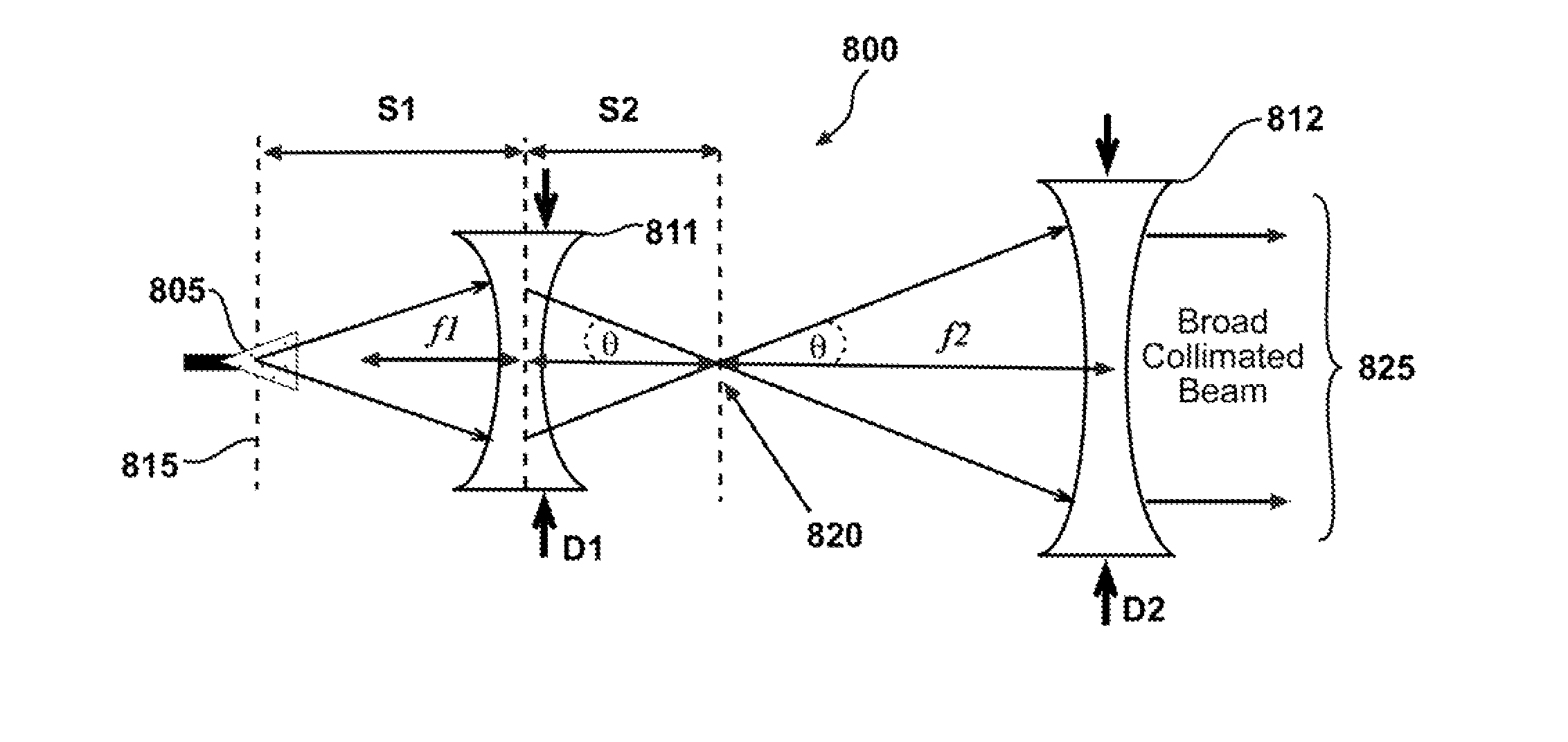
[0024]An objective of the present invention is to guide and control the energy radiated from a narrowband microwave source into a collimated microwave beam. The diameter of the collimated microwave beam can be varied as desired, to thereby control the area being illuminated at large distances. The present invention includes a pyramidal horn antenna and two specially designed parallel plate spherical waveguide lenses that together provide a novel way to transform energy generated by a high power microwave source into a collimated microwave beam. Collimation of the narrowband microwave energy is achieved by proper design and placement of the lenses. The diameter of the collimated microwave beam is controlled by translating these lenses relative to the phase center of a pyramidal horn antenna and relative to each other along the boresight axis of the horn antenna, with the optical axes of the lenses lying along the boresight. The entire antenna system can also be rotated in the azimuth...


PUM


Abstract

A zoom antenna includes an ordinary pyramidal horn antenna with either a coaxial or waveguide feed and two parallel plate waveguide lenses (commonly referred to as “metal plate lenses”) positioned with their optical axes collinear with the boresight of the pyramidal horn antenna and aligned with their plates parallel to the electric field vector. The zoom antenna outputs a collimated microwave beam having a diameter varied by translation of the lenses along boresight relative to each other and relative to the phase center of the horn antenna. The zoom antenna can be rotated to vary the azimuth and elevation angles of the collimated microwave beam produced therefrom, to thereby aim the beam in any direction.

Description

STATEMENT REGARDING FEDERALLY SPONSORED RESEARCH OR DEVELOPMENT[0001]The conditions under which this invention was made are such as to entitle the Government of the United States under paragraph 1(a) of Executive Order 10096, as represented by the Secretary of the Air Force, to the entire right, title and interest therein, including foreign rights.FIELD OF THE INVENTION[0002]The present invention relates to microwave antennas used in narrowband applications, and, more particularly, to a microwave antenna that incorporates parallel plate waveguide lenses, commonly referred to as “metal plate lenses,” disposed in association with an ordinary pyramidal horn antenna having either a coaxial or waveguide feed, to produce a collimated microwave beam having a diameter which can be varied. A microwave is an electromagnetic wave with a wavelength in the range of 0.001 to 0.3 meters. The terms “microwave” and “electromagnetic wave” are used interchangeably herein.BACKGROUND[0003]It is often de...

Claims


Application Information

Patent Timeline
IPC IPC(8): H01Q19/06H01Q13/02
CPCH01Q19/062H01Q13/02H01Q15/04H01Q19/08
Inventor LAWRANCE, JULIE E.
Owner THE GOVERNMENT OF THE US SEC THE AIR FORCE
Why Eureka
Try Eureka