Ultrasonic type flowmeter apparatus and method of using the same

a flowmeter and ultrasonic technology, applied in the direction of liquid/fluent solid measurement, instrumentation, testing/calibration for volume flow, etc., can solve the problems of inability to make the conduit by a single molding of synthetic resin, inability to smoothly flow through the conduit, and inability to accurately correct the conduit, etc., to achieve the effect of reducing the running cost of the whole system and accurate correction

Active Publication Date: 2017-03-07
ATSUDEN
View PDF39 Cites 7 Cited by
  • Summary
  • Abstract
  • Description
  • Claims
  • Application Information

AI Technical Summary

Benefits of technology

[0013]The present invention has for its object to provide a novel and useful ultrasonic type flow sensor which can remove the above mentioned drawbacks of the known flowmeter apparatuses and can attain a high measurement precision by deriving calibration data before measurement, storing the thus derived calibration data in a memory installed in a disposable conduit, and reading the thus stored calibration data into a repeatedly used electrical measuring circuit upon the actual measurement.
[0026]In the ultrasonic type flowmeter apparatus according to the invention, the calibration data is stored in the memory portion fixed to the disposable conduit, upon the actual measurement the calibration data stored in the memory portion is read into the electrical measuring circuit portion which is non-disposable, and the ultrasonic signals generated from the ultrasonic signal transmission and reception elements are processed in the electrical measuring circuit portion in accordance with the calibration data. In this manner, it is possible to derive the flow rate accurately corrected by the calibration data. Moreover, the rather expensive electrical measuring circuit portion can be used repeatedly, and therefore a running cost of the whole system can be reduced.

Problems solved by technology

It is difficult to make the conduit by a single molding of synthetic resin.
Moreover, centerlines of the fused parts might not be coincided with each other, and therefore a liquid could not flow through the conduit smoothly and an undesired turbulence might be generated.
Furthermore, a length and an inner diameter of the straight portion might include error and a precision of securing the ultrasonic signal transmission and reception elements might be lowered.

Method used


Image

  • Ultrasonic type flowmeter apparatus and method of using the same
  • Ultrasonic type flowmeter apparatus and method of using the same
  • Ultrasonic type flowmeter apparatus and method of using the same

Examples


embodiment 1

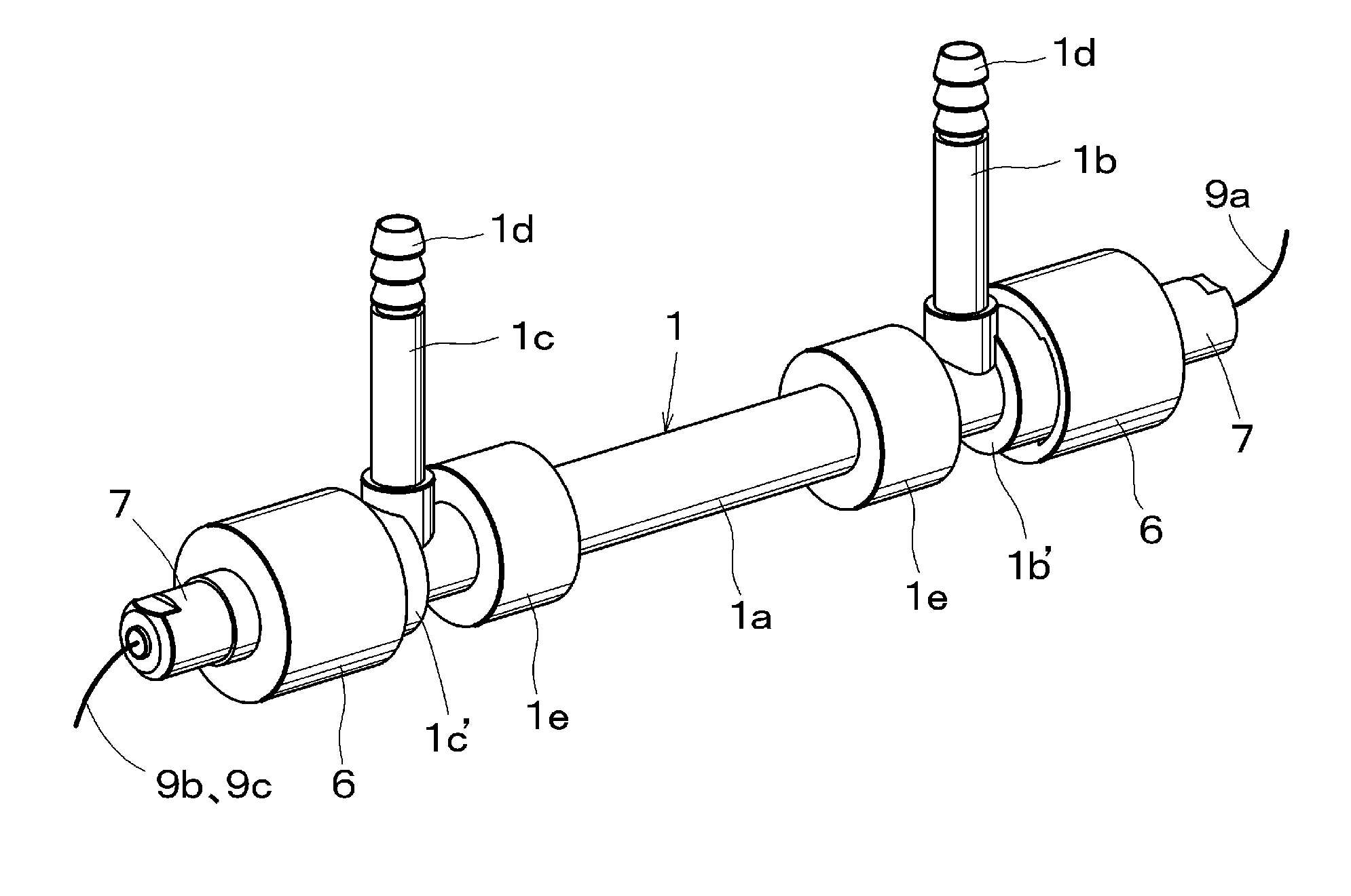
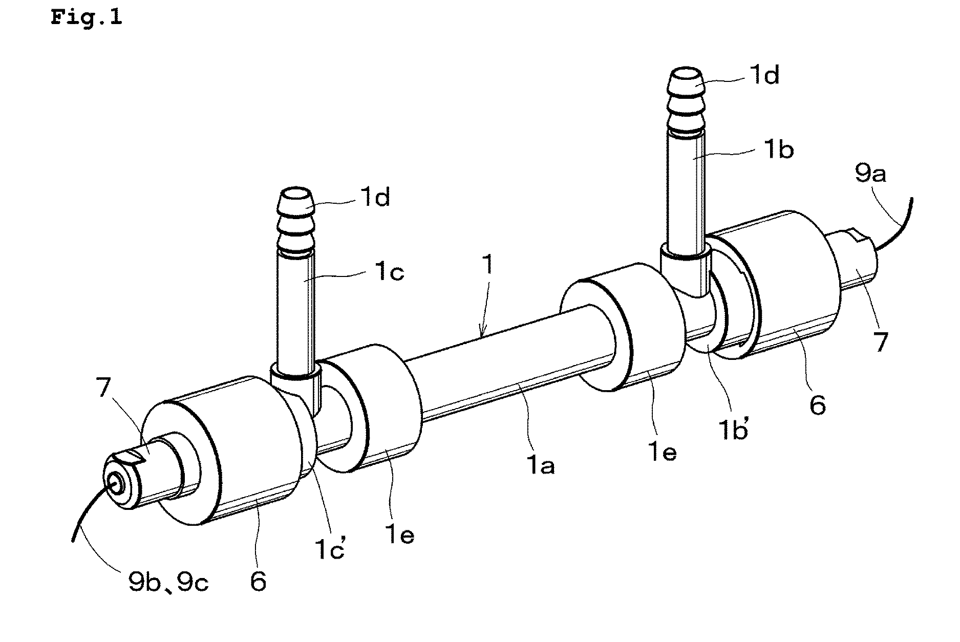
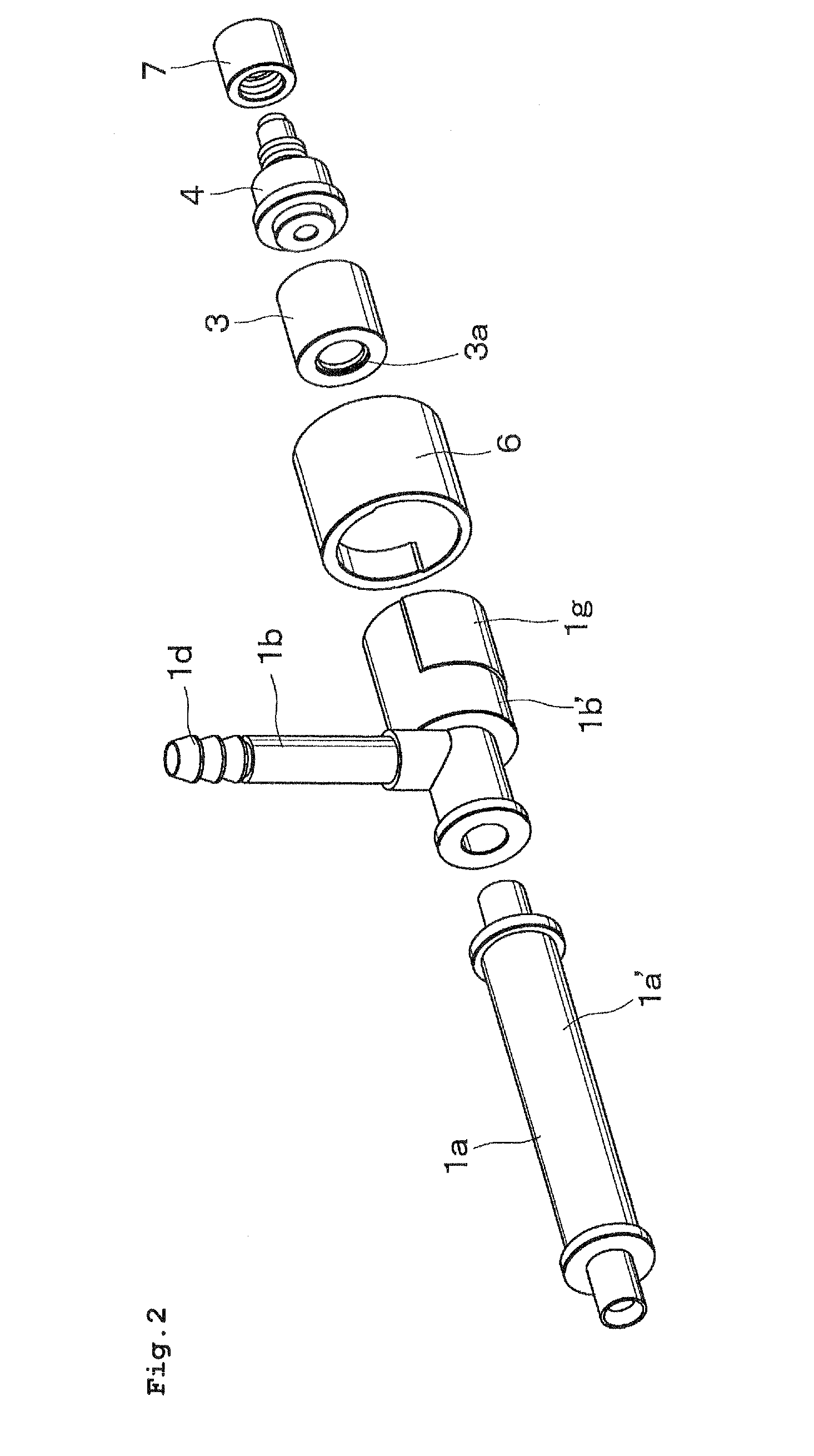
[0035]Now embodiments of the ultrasonic flow sensor according to the invention will be explained in detail with reference to the attached drawings. FIGS. 1, 2 and 3 are a perspective view, an exploded perspective view and a cross sectional view, respectively showing a disposable conduit of the first embodiment of the ultrasonic type flowmeter apparatus according to the invention. It should be noted that in FIG. 2, a lower stream portion of the conduit is not shown, because the conduit has a symmetrical construction.

[0036]The conduit 1 made of a synthetic resin such as polypropylene and Teflon (registered trade mark) comprises a straight pipe portion 1a, an inlet pipe portion 1b and an outlet pipe portion 1c. The inlet and outlet pipe portions 1b and 1c are coupled with the straight pipe portion 1a at its both ends such that these pipe portions 1b and 1c extend perpendicularly to the straight pipe portion 1a to form a so-called crank-shape conduit.

[0037]The straight pipe portion 1a, ...


PUM


Abstract

A disposable conduit 1 includes piezo-electric elements 2a and 2b and a memory chip 10 in which calibration data specific to the relevant conduit is stored. Before measurement, a non-disposable electrical measuring circuit reads the calibration data out of the memory chip 10 to prepare a calibrating equation or a calibration table. A flow speed of a blood passing through the conduit or a flow rate calculated from the flow speed is corrected in accordance with the calibrating equation or calibration table.

Description

BACKGROUND OF THE INVENTION[0001]Field of the Invention[0002]The present invention relates to an ultrasonic type flowmeter apparatus and a method of using the same. Particularly, the present invention relates to an ultrasonic type flowmeter apparatus preferably used in a cardiac surgery for measuring a flow rate of a blood flowing through an auxiliary heart, in which a part of the ultrasonic type flowmeter apparatus is disposed in order to avoid undesired infection.[0003]Related Art Statements[0004]The ultrasonic type flowmeter apparatus comprises a conduit having, for instance a crank shape, and a pair of piezo-electric transducer elements each serving as an ultrasonic signal transmission and reception element are provided at both ends of a straight portion of the conduit. To this end, the conduit must include fitting portions, and furthermore the conduit has to comprise an inlet portion and an outlet portion. It is difficult to make the conduit by a single molding of synthetic res...

Claims


Application Information

Patent Timeline
Patent Type & Authority Patents(United States)
IPC IPC(8): G06F15/00G01F25/00G01F1/66
CPCG06F15/00G01F1/662G01F1/667G01F1/668G01F25/0007G01F25/10
Inventor MURAKAMI, EIICHI
Owner ATSUDEN
Why Eureka
Try Eureka