
Array substrate and method of mounting integrated circuit using the same

a technology of array substrate and integrated circuit, which is applied in the direction of sustainable manufacturing/processing, instruments, final product manufacturing, etc., can solve the problems of misalignment between the bumps of the driving integrated circuit and the pads of the pad unit, and achieve the effect of preventing misalignmen

Active Publication Date: 2017-03-07
SAMSUNG DISPLAY CO LTD
View PDF19 Cites 20 Cited by
  • Summary
  • Abstract
  • Description
  • Claims
  • Application Information

AI Technical Summary

Benefits of technology

This design effectively prevents misalignment and ensures proper mounting of the integrated circuit by calculating and adjusting for substrate expansion or contraction, improving mounting efficiency and reliability.

Problems solved by technology

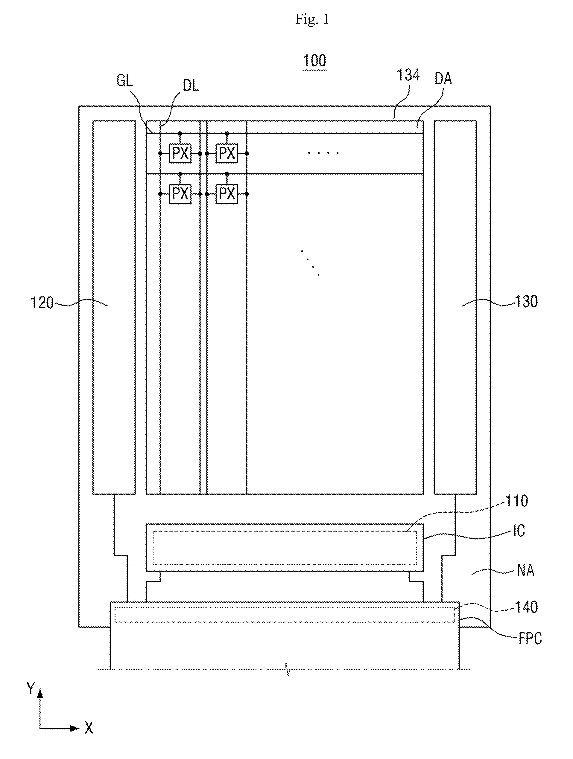
However, the size of a flexible array substrate may change during processes, which are then followed by the formation of a pad unit, thereby causing misalignment between the bumps of a driving integrated circuit and the pads of the pad unit.

Method used


Image

  • Array substrate and method of mounting integrated circuit using the same
  • Array substrate and method of mounting integrated circuit using the same
  • Array substrate and method of mounting integrated circuit using the same

Examples


Embodiment Construction

[0026]In the following description, for the purposes of explanation, numerous specific details are set forth in order to provide a thorough understanding of various exemplary embodiments. It is apparent, however, that various exemplary embodiments may be practiced without these specific details or with one or more equivalent arrangements. In other instances, well-known structures and devices are shown in block diagram form in order to avoid unnecessarily obscuring various exemplary embodiments.

[0027]In the accompanying figures, the size and relative sizes of layers, films, panels, regions, etc., may be exaggerated for clarity and descriptive purposes. Also, like reference numerals denote like elements.

[0028]When an element or layer is referred to as being “on,”“connected to,” or “coupled to” another element or layer, it may be directly on, connected to, or coupled to the other element or layer or intervening elements or layers may be present. When, however, an element or layer is re...


PUM

PropertyMeasurementUnit
inclination angleaaaaaaaaaa
rectangular shapeaaaaaaaaaa

Abstract

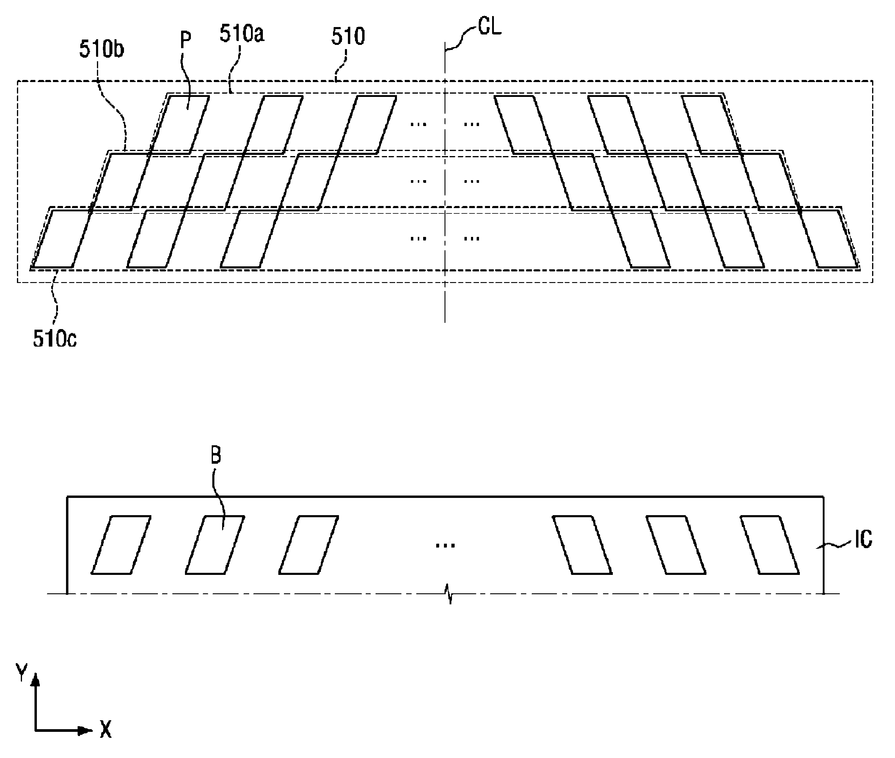
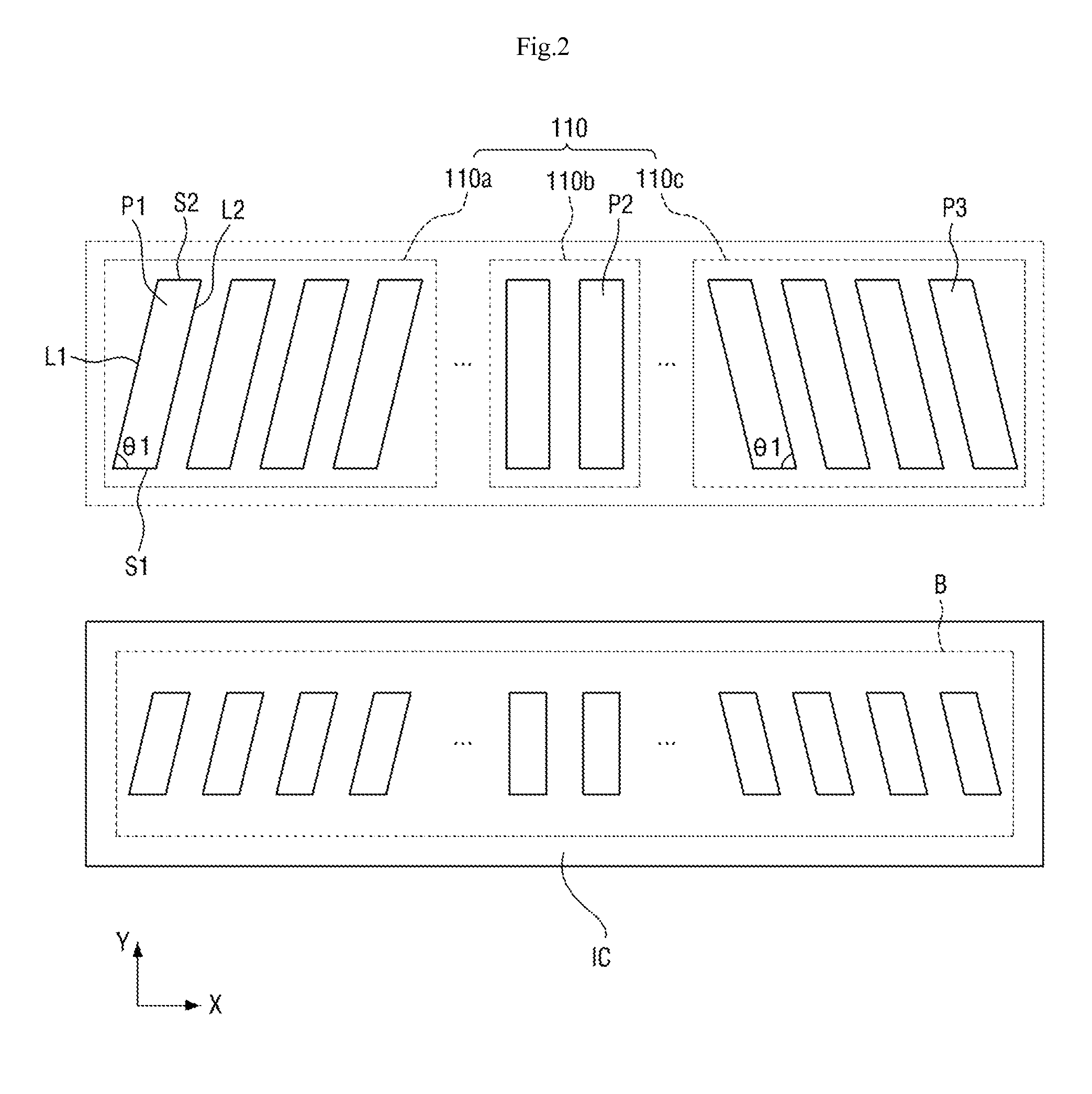
An array substrate including a display area and a non-display area surrounding the display area. The non-display area includes a pad portion including one or more first pads that each have a parallelogram shape.

Description

CROSS-REFERENCE TO RELATED APPLICATION[0001]This application claims priority from Korean Patent Application No. 10-2014-0073756, filed on Jun. 17, 2014, which is hereby incorporated by reference for all purposes as if fully set forth herein.BACKGROUND[0002]Field[0003]Exemplary embodiments relate to a method of mounting an integrated circuit using an array substrate.[0004]Discussion of the Background[0005]A display device, such as a liquid crystal display (LCD) device or an organic light-emitting diode (OLED) device, may include an array substrate, which has a display area and a non-display area surrounding the display area. The array substrate may be used as a circuit board for separately driving pixels of the display device. Gate wiring for transmitting a scan signal, data wiring for transmitting an image signal, thin-film transistors (TFTs), and various organic or inorganic insulating layers may be provided on the array substrate. Each of the TFTs include a gate electrode that for...

Claims


Application Information

Patent Timeline
Patent Type & Authority Patents(United States)
IPC IPC(8): H01L23/48G02F1/1345H05K1/11H05K1/18H10K99/00
CPCH05K1/111G02F1/13458H05K1/189H05K2201/09381H05K2201/09418H05K2201/09427H05K2201/09709H05K2201/09954H05K2201/10128H05K2203/166Y02P70/611Y10T29/49005Y02P70/50Y02E10/549H10K59/131H10K77/111H10K2102/311H01L24/05H01L24/06H01L24/81H01L27/124H01L2224/05552H01L2224/06152H01L2224/81132H01L2924/3511
Inventor LEE, DAE GEUN
Owner SAMSUNG DISPLAY CO LTD
Learn More