Apparatus for arranging and transferring ammunition using controlled magnetic force

a magnetic force and ammunition technology, applied in the direction of conveyors, conveyor parts, transportation and packaging, etc., can solve the problems of increasing the size and radius of the shuttle at a geometric rate, increasing the possibility that not all the cartridges will succeed in being completely transferred, and increasing the load applied to the drive column supporting and rotating the circular shuttle, etc., to achieve the effect of increasing the speed of the conveyor, increasing the speed of the separation of cartridges, and optimizing the magnetic for

Active Publication Date: 2017-03-14
POONGSAN CO LTD
View PDF18 Cites 27 Cited by
  • Summary
  • Abstract
  • Description
  • Claims
  • Application Information

AI Technical Summary

Benefits of technology

The present invention aims to provide a new and improved apparatus for arranging and transferring ammunition using a magnetic slope conveyor. The apparatus is designed to overcome the problems and limitations of current systems by appropriately arranging cartridges, applying magnetic force to transfer them to precise locations, and releasing the magnetic force at the appropriate point after the arrangement is complete. The apparatus can adjust the magnetic force based on the position of the magnetizing controller or the expected distribution of cartridges on the transfer track, and it can increase the speed of the conveyor. The technical effects of the invention include reducing the space required for installation, flexibly responding to vary in cartridge size and weight, minimizing cartridge escape from the magnet, and remarkably increasing processing speed to the point at which the cartridges are finally loaded or supplied. Additionally, the invention includes the use of a slit sifter, a demagnetizer, and other technical components to further support the technical idea of the invention.

Problems solved by technology

The horizontal transfer type of arranging and transferring apparatus, which is equipped with the circular shuttle, has a disadvantage in that the size and radius of the shuttle have to be increased at a geometric rate with increased size of cartridges, and the load applied to a drive column for supporting and rotating the circular shuttle, which has a radial shape, is also steeply increased.
However, since only the bullet portion of a cartridge, which is capable of being adhered to a magnet and has a small surface area relative to the entire surface of the cartridge, is burdened with the total weight of the cartridge, there is still a disadvantage in that the bullet portion is easily separated from the magnet when there is interference between adjacent cartridges, thereby increasing the possibility that not all of the cartridges will succeed in being completely transferred.
If the magnetic force is simply increased in order to overcome the above disadvantage, however, the cartridge cases of cartridges do not hang by themselves, because cartridges are more intensively agglomerated or adhered to each other, thereby making it impossible to attain the originally intended arranging effects.

Method used


Image

  • Apparatus for arranging and transferring ammunition using controlled magnetic force
  • Apparatus for arranging and transferring ammunition using controlled magnetic force
  • Apparatus for arranging and transferring ammunition using controlled magnetic force

Examples


Embodiment Construction

[0049]In order to assist in specifically explaining means for solving the above-described problems, embodiments of the present invention will be described in detail with reference to the accompanying drawings.

[0050]However, the components and the combinations thereof which are expressed by specific technical terms in the embodiments, which will be disclosed below, should not be construed as restricting the technical idea of the present invention.

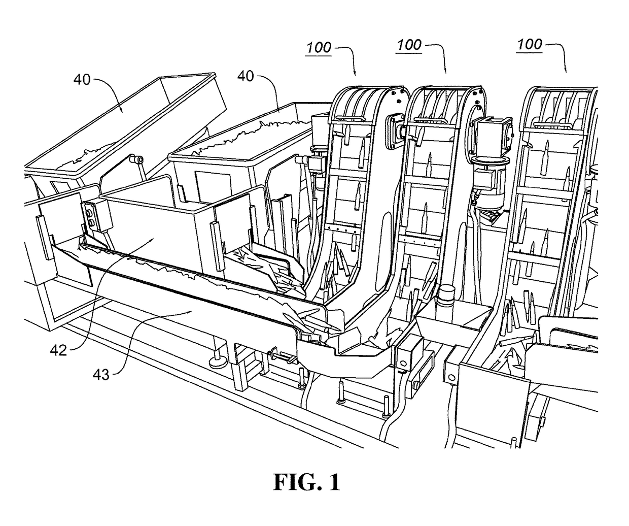
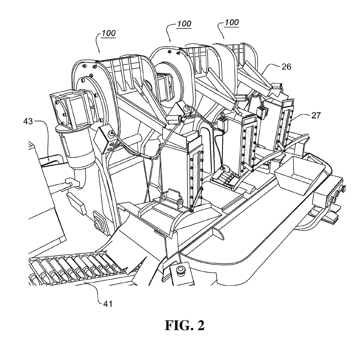
[0051]FIGS. 1 and 2 show a cartridge-supplying apparatus suitable for manufacturing cartridge belts, comprising three apparatuses 100 for arranging and transferring ammunition according to the present invention.

[0052]Referring to FIG. 1 (front side) and FIG. 2 (back side), when it is intended to manufacture a cartridge belt in which two kinds of cartridges are arranged (for example, common cartridges and tracer cartridges for a heavy machine gun, having a bullet diameter of 12.7 mm) in a fashion in which one tracer cartridge is arranged for ...


PUM


Abstract

An apparatus for arranging and transferring ammunition, includes a slope conveyor, which is configured into an endless track structure so as to lift cartridges placed on a transfer track thereof using magnetic force, a plurality of permanent magnets, which are arranged on the slope conveyor so as to create a magnetic field outside the transfer track, one or more hole sifters, which are disposed near an outer surface of the transfer track and which have cartridge passage holes formed at locations through which the plurality of permanent magnets pass, and magnetizing controllers including electromagnets, which are disposed above and under the hole sifters and are assigned to the plurality of permanent magnets, wherein the magnetizing controllers detect a position of the permanent magnet when the permanent magnet passes through the cartridge passage hole, and controls the electromagnets to create a magnetic field, having polarity, orientation and density at least one of which is controlled, above or under the hole sifters.

Description

BACKGROUND OF THE INVENTION[0001]Field of the Invention[0002]The present invention relates to an apparatus for arranging and transferring ammunition, which is constructed to rapidly and evenly arrange cartridges, which are supplied in a disordered state and then to supply the cartridges side by side to a subsequent processing unit, using the tendency whereby a steel bullet fitted in a cartridge adheres to a magnet.[0003]Description of the Related Art[0004]Most ammunition is manufactured in a such a way as to charge propellant into a cartridge case, to fit a bullet into the cartridge case and to finally press the connected portion therebetween in a sealing manner. Cartridges manufactured in this way are commonly contained in a cart in a disordered state.[0005]In order to execute quality inspection of individual cartridges, to manufacture a cartridge belt from cartridges, or to individually prepare packages containing cartridges numbering in the teens or several tens thereof, there is...

Claims


Application Information

Patent Timeline
IPC IPC(8): B65G17/46B65G17/48B65G47/34B65G21/20
CPCB65G17/48B65G17/46B65G21/2063B65G47/34B65G47/1485
Inventor LEE, DONG HEE
Owner POONGSAN CO LTD
Why Eureka
Try Eureka