Temporary portable abatement, remediation, demolition, and remodeling door

a temporary door and frame technology, applied in the field of doors, can solve the problems of reducing the door panel and its frame are typically non-transparent and non-removable by users after installation, and the cost of recouping the cost of purchasing disposable zippered doorway kits, so as to reduce air transmission and facilitate secure/locking

Inactive Publication Date: 2017-03-21
CALI JOHN E
View PDF29 Cites 1 Cited by
  • Summary
  • Abstract
  • Description
  • Claims
  • Application Information

AI Technical Summary

Benefits of technology

[0012]The primary objective of this invention is to provide a reusable and portable temporary door/frame assembly for abatement, remediation, demolition, and remodeling applications (such as for dust containment, limiting access to temporary structural and material hazards, and the elimination of mold, asbestos, or lead, but not limited thereto), which is used with a temporary containment enclosure or barrier to allow quick/easy ingress and egress to/from limited access areas where containment of construction debris, drywall dust, mold, or other potentially harmful structural hazards and materials is desired. It is also an objective of this invention to provide an enhanced temporary door system which can be installed by one person in less than 10 minutes. A further object of this invention is to provide a reusable and portable temporary door/frame assembly that allows easy passage through it without bending, stretching, ducking, or a tripping hazard. Additionally, it is an objective of this invention to provide means for easy ingress/egress by owner

Problems solved by technology

Furthermore, if used repeatedly, its cost will soon be recovered over the repeat expense of purchasing disposable zippered doorway kits.
Furthermore, although the present invention door/frame assembly has a door frame hinged

Method used


Image

  • Temporary portable abatement, remediation, demolition, and remodeling door
  • Temporary portable abatement, remediation, demolition, and remodeling door
  • Temporary portable abatement, remediation, demolition, and remodeling door

Examples


Embodiment Construction

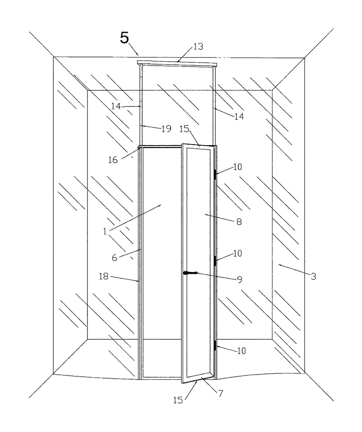
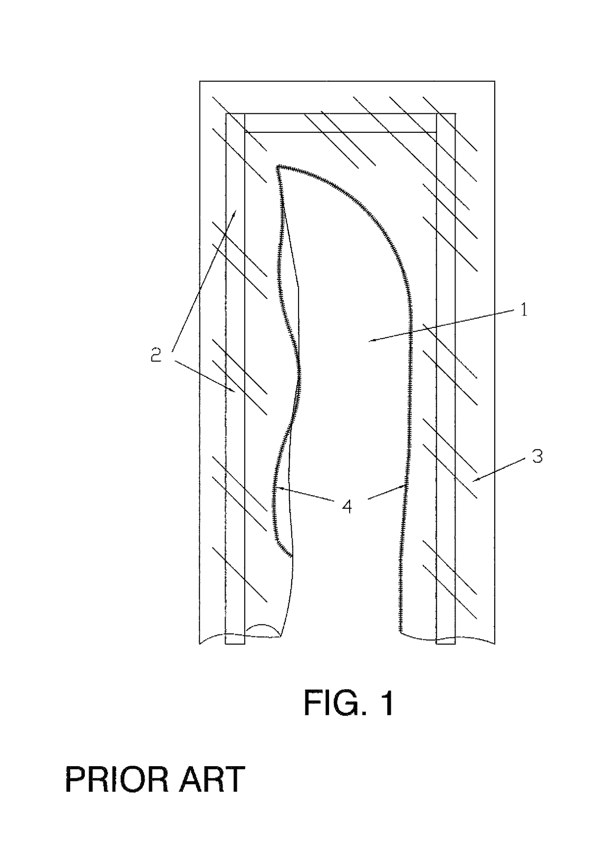
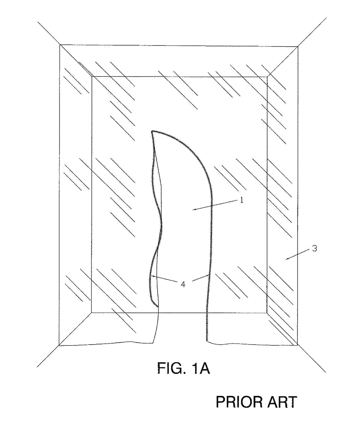
[0046]The present invention is a reusable and portable temporary door and frame assembly 5 primarily used in abatement, remediation, demolition, and remodeling applications (such as for dust containment and the elimination of mold, asbestos, or lead, but not limited thereto), which is used with a wall of a temporary containment enclosure or barrier (see the number 3 in FIGS. 1, 1A, 7, and 8, or other) to allow quick and easy ingress and egress, without bending, stretching, ducking, or a tripping hazard, to / from limited access areas where containment therein of construction debris, drywall dust, mold, asbestos, or other potentially dangerous or hazardous materials is desired. The present invention assembly 5 comprises lightweight materials, such as but not limited to plastic or aluminum, and integral to its outer frame portion 6 are two non-spring-loaded telescopic poles (side members 14) that extend a top bar / piece 13 upwardly and away from the assembly's outer frame 6 for attachmen...


PUM


Abstract

A reusable and portable temporary door/frame assembly primarily used in abatement, remediation, demolition, and remodeling applications with a containment enclosure or barrier to allow quick and easy ingress/egress, or restrict movement, to/from a limited access area. The assembly comprises lightweight materials, such as but not limited to plastic or aluminum, and two non-spring-loaded telescopic poles that extend a top bar/piece upwardly for attachment to an overhead door frame, header, or ceiling. The top of the frame is also configured to accept two upwardly extendable spring-loaded/biased poles allowing a containment enclosure or barrier to be built to ceiling heights beyond the reach of the integral telescopic poles. Since the assembly is portable, it can be installed to open inwardly, outwardly, and is reversible, depending on convenience or need. The door is lockable. The door panel's frame includes a seal at the top/bottom to reduce air transmission to/from the limited access area.

Description

CROSS-REFERENCES TO RELATED APPLICATIONS[0001]NoneBACKGROUND OF THE INVENTION[0002]Field of the Invention[0003]The invention relates to doors, specifically to a reusable and portable temporary door and frame assembly primarily used in abatement, remediation, demolition, and remodeling applications (such as for dust containment and the elimination of mold, asbestos, or lead, but not limited thereto). It is typically employed with a temporary containment wall, temporary containment enclosure, existing doorway, entrance, or other enlarged wall opening adjacent to a limited access area to allow quick and easy ingress and egress to / from the limited access area within which it is desired to contain construction debris, drywall dust, or other materials having a potential health risk or otherwise causing a difficult, time-consuming, and / or expensive clean up process if not contained. Once the present invention is installed, which typically takes one person less than 10 minutes, there is no ...

Claims


Application Information

Patent Timeline
IPC IPC(8): E04G21/24E04G21/30E06B9/06E06B9/01E06B7/18
CPCE04G21/24E04G21/30E06B9/06E06B9/01E06B7/18E04G21/243E06B2009/015Y10S52/12
Inventor CALI, JOHN E.
Owner CALI JOHN E
Why Eureka
Try Eureka