Alloy material for R-T-B system rare earth permanent magnet, method for producing R-T-B system rare earth permanent magnet, and motor

a rare earth permanent magnet and rtb system technology, applied in the direction of magnetic materials, inductance/transformer/magnet manufacturing, magnetic bodies, etc., can solve the problems of uneven distribution of dy, unstable supply of dy, and limited output, so as to achieve high coercivity, favorable use of a motor, and high orientation rate

Active Publication Date: 2017-03-21
TDK CORPARATION
View PDF27 Cites 0 Cited by
  • Summary
  • Abstract
  • Description
  • Claims
  • Application Information

AI Technical Summary

Benefits of technology

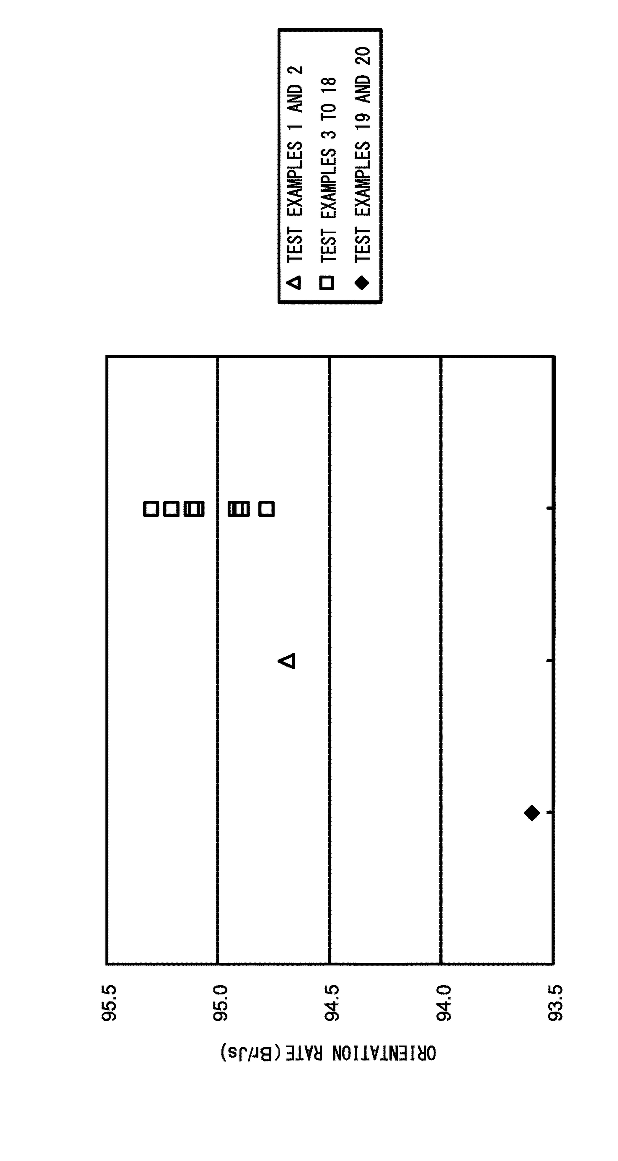
[0038]An alloy material for an R-T-B system rare earth permanent magnet of the invention includes a plurality of R-T-B system alloys having different compositions and a metal powder, the respective R-T-B system alloys are formed of R which is composed of two or more kinds selected from rare earth elements, T which is composed of a transition metal essentially containing Fe, B, and unavoidable impurities, a first alloy having the greatest Dy content among the plurality of R-T-B system alloys contains 17 mass % or greater of Dy, and a Dy concentration difference between the first alloy and a second alloy having the least Dy concentration difference with respect to the first alloy among the plurality of R-T-B system alloys is 5 mass % or greater. Accordingly, by molding and sintering the alloy material, it is possible to provide an R-T-B system rare earth permanent magnet with a high orientation rate and high coercivity which is favorably used in a motor and has excellent magnetic properties.

Problems solved by technology

However, Dy is unevenly distributed and its output is also limited.
Accordingly, the supply of Dy is unstable.

Method used


Image

  • Alloy material for R-T-B system rare earth permanent magnet, method for producing R-T-B system rare earth permanent magnet, and motor

Examples


examples

[0075]An Nd metal (having a purity of 99 wt % or greater), a Dy metal (having a purity of 99 wt % or greater), ferroboron (Fe 80%, B 20 w %), a Co metal (having a purity of 99 wt % or greater), an Al metal (having a purity of 99 wt % or greater), a Cu metal (having a purity of 99 wt % or greater), and iron lump (having a purity of 99 wt % or greater) were weighted to obtain component compositions of alloys A to D shown in Table 1, and charged in an alumina crucible

[0076]

TABLE 1(wt %)Total RNdDyBCoAlCuFeA30.030.00.00.941.00.150.10bal.B31.027.04.00.941.00.150.10bal.C31.022.09.00.941.00.150.10bal.D33.09.024.00.941.00.150.10bal.

[0077]Thereafter, the alumina crucible was put in a high-frequency vacuum induction furnace, the air in the furnace was replaced by Ar, and heating to 1450° C. was performed to melt the metals to thereby obtain a molten metal. Next, the molten metal was poured into a water-cooled copper roll, and cast alloy flakes in which an average thickness was controlled to a...


PUM

PropertyMeasurementUnit
sizeaaaaaaaaaa
grain sizeaaaaaaaaaa
temperatureaaaaaaaaaa

Abstract

An alloy material for an R-T-B system rare earth permanent magnet having a high orientation rate and high coercivity (Hcj), and a method for producing an R-T-B system rare earth permanent magnet using the alloy material. The alloy material includes a plurality of R-T-B system alloys having different compositions and a metal powder. The respective R-T-B system alloys are formed of R which is composed of two or more kinds selected from rare earth elements, T which is composed of a transition metal essentially containing Fe, B, and unavoidable impurities. A first alloy having the greatest Dy content contains 17 mass % or greater of Dy, and a Dy concentration difference between the first alloy and a second alloy having the smallest Dy concentration difference with respect to the first alloy among the plurality of R-T-B system alloys is 5 mass % or greater.

Description

CROSS REFERENCE TO RELATED APPLICATIONS[0001]This application is a National Stage of International Application No. PCT / JP2011 / 070042 filed Sep. 2, 2011, claiming priority based on Japanese Patent Application No. 2010-221482 filed Sep. 30, 2010, the contents of all of which are incorporated herein by reference in their entirety.TECHNICAL FIELD[0002]The present invention relates to an alloy material for an R-T-B system rare earth permanent magnet, a method for producing an R-T-B system rare earth permanent magnet, and a motor, and particularly, to an alloy material for an R-T-B system rare earth permanent magnet from which an R-T-B system rare earth permanent magnet which has excellent magnetic properties and is favorably used in a motor is obtained, a method for producing an R-T-B system rare earth permanent magnet using the alloy material, and a motor.BACKGROUND ART[0003]Hitherto, R-T-B system rear earth permanent magnets (hereinafter, may be referred to as “R-T-B system magnet”) ha...

Claims


Application Information

Patent Timeline
Patent Type & Authority Patents(United States)
IPC IPC(8): C22C38/00H01F1/057H01F41/02C22C38/06B22F1/00H02K21/00C22C33/02C22C1/02H01F1/06C22C38/16C22C38/10
CPCH02K21/00B22F1/0003C22C1/02C22C33/0278C22C38/002C22C38/005C22C38/06C22C38/10C22C38/16H01F1/0577H01F1/06H01F41/0266B22F1/09
Inventor NAKAJIMA, KENICHIROYAMAZAKI, TAKASHI
Owner TDK CORPARATION
Why Eureka
Try Eureka