Method and apparatus for supplying heated, pressurized air

a technology of pressurized air and heating method, which is applied in the direction of water supply installation, machine/engine, pipe heating/cooling, etc., can solve the problems of increasing the process step, inefficient methods, and inability to allow a gas turbine or aero-derivative gas turbine engine to provide all of the heated, pressurized air, etc., to achieve the effect of reducing the role of any downstream heater, maximizing reliability and reducing energy requirements

Active Publication Date: 2017-03-28
INV PROPYLENE LLC
View PDF26 Cites 1 Cited by
  • Summary
  • Abstract
  • Description
  • Claims
  • Application Information

AI Technical Summary

Benefits of technology

[0012]Furthermore, the systems and methods of this application reduce the energy required for heating and pressurizing the air from ambient conditions to process requirements, by performing most of the heating and pressurizing functions all within the engines. Use of the engines reduces the need for separate heaters or compressors to heat and pressurize the air. Because the engines are supplying the majority of the heat in the discharge air, the use of separate downstream heaters, if any, can be used only for fine tuning, or micro-heating the air. Because the role of any downstream heater is reduced, loss of the heater, such as, for example, for replacement or repair, will not cause a plant shutdown. In at least one embodiment, the engines supply all the heat necessary for the process during standard operation.
[0013]In this manner, the embodiments of this application serve the dual purposes of supplying an efficient means of heating and compressing air in one single step, while also maximizing reliability through use of multiple gas turbine engines.
[0014]In addition, the embodiments disclosed below include a manifold for stabilizing the engines and minimizing movement between system parts. Also disclosed are expansion joints for placement between the engines and other system parts, which allows for sonic relative movement between the engine and the other system parts. The manifolds and expansion joints are operable to dampen and manage vibrations and other movements associated with the engines that could otherwise be problematic.
[0016]The system can also include a manifold connected to the engine, to substantially constrain movement of the engine relative to the pipe in a non-axial direction. Furthermore, the system can include a nozzle located in the flow path between, and in fluid communication with, the engine and the device in the industrial process, the nozzle tapering from a larger diameter toward the engine, to a smaller diameter in a central portion of the nozzle, and back to a larger diameter toward the device in the industrial process, so that as air passes through the nozzle, the flow rate of the air increases and the pressure decreases. A heater can be positioned between the engine and the device, to further adjust the temperature of the air. In one certain embodiment, the process device is a reaction chamber, and the industrial process is a polypropylene manufacturing process.
[0019]In some embodiments, the system can further include an expansion joint which can be located between the pipe and the exhaust end of the engine. The expansion joint preferably has a central axis co-linear with the central axis of the pipe and the exhaust end of the engine, and allows for axial relative movement between the pipe and the exhaust end of the engine.
[0022]Yet another embodiment of the current application includes a method for providing heated, pressurized air for an industrial process. The method includes the step of drawing ambient air into engine, the engine having an intake end, an exhaust end, and a central axis, wherein the air is drawn into the intake end of the engine. The method further includes the steps of heating and pressurizing the air within the engine, and expelling the heated, pressurized air from the exhaust end of the engine, the heated, pressurized air being of sufficient heat and pressure to meet the needs of a process device of an industrial process. In addition, the method further includes the steps of transporting the heated, pressurized air from the exhaust end of the engine to the process device of the industrial process with a pipe, the engine being secured to an immovable base so as to prevent substantially all non-axial movement of the engine relative to the pipe.

Problems solved by technology

However, such methods tend to be inefficient and costly in applications where very high heat and high pressure are needed.
To date, however, no system has been developed that is capable of allowing a gas turbine or aero-derivative gas turbine engine to provide all of the heated, pressurized air necessary to meet process requirements.
Currently, for example, systems that use exhaust from such an engine often require further pressurization of the air with independent compressors.
This not only adds a step to the process, but adds cost to the operation of the facility.
In addition, if the engine or a compressor is shut down for maintenance or repair, or fails for some other reason, the industrial process must be stopped, leading to expensive plant shutdowns and restarting operations.
Additional problems result from the vibrations in the gas turbine or aero-derivative gas turbine engine, which tend to cause the engine to become misaligned with the piping designed to carry the exhaust to the industrial process.
In addition, the piping connected to the exhaust of the gas turbine or aero-derivative engine tends to expand after start-up, creating undue stress in the joint between the piping and the exhaust, and causing allure of that joint.
Accordingly, such engines are not designed to produce exhaust having the particular pressure and temperature characteristics required by a given industrial process.

Method used


Image

  • Method and apparatus for supplying heated, pressurized air
  • Method and apparatus for supplying heated, pressurized air
  • Method and apparatus for supplying heated, pressurized air

Examples


example

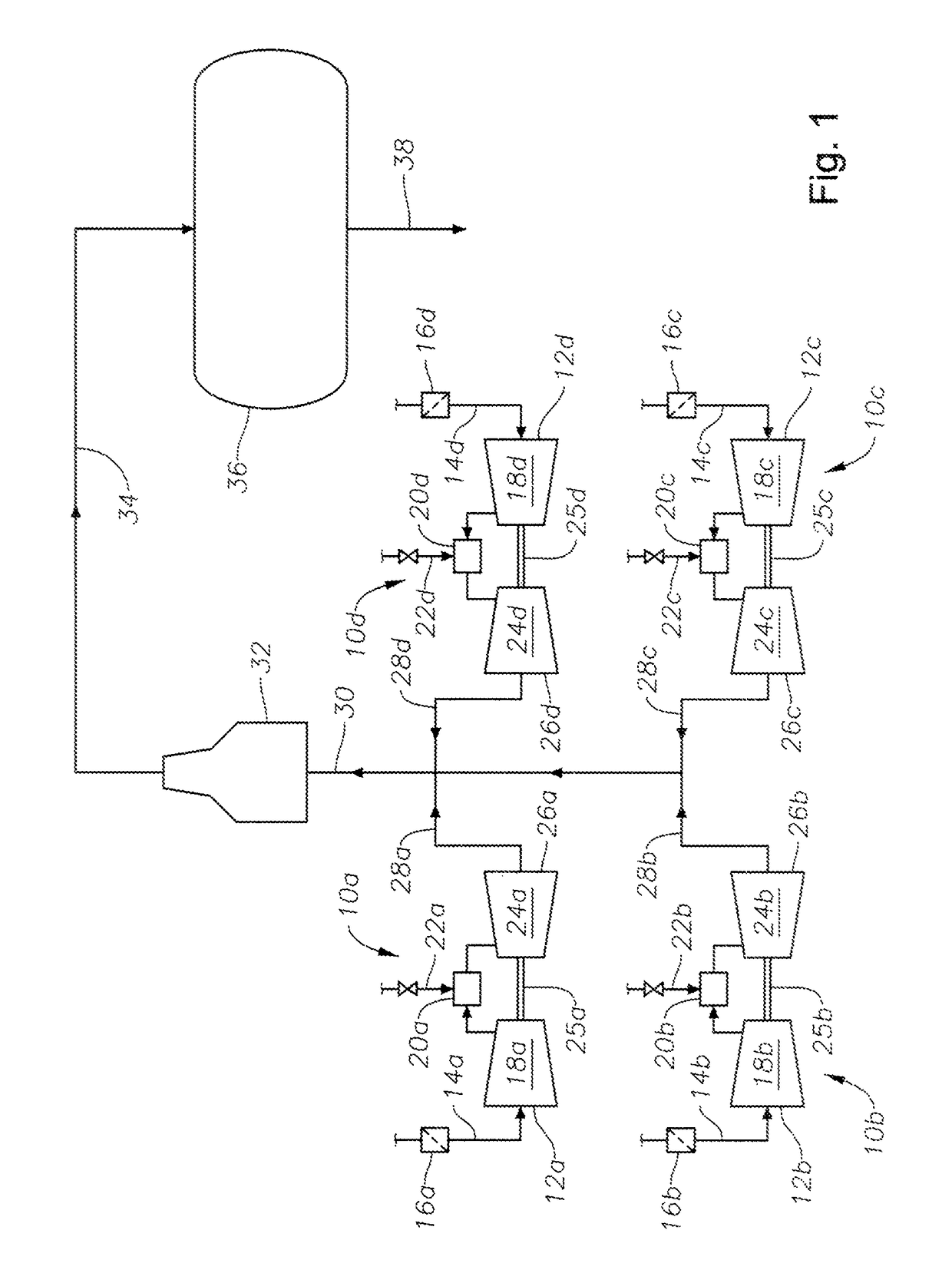
[0046]This example provides information relating to an industrial process with which an embodiment of the current application can be used. Although the following description of the example includes the reference numbers from FIG. 1, it is to be understood that that the example is also applicable to other embodiments as well. In the example, the industrial process requires air to reach the process device 36 with the following parameters:

Temperature: 1200 to 1250 deg F.

Pressure: 10 to 15 psig

Flow Rate: 2,000,000 to 2,500,000 lbs per hour

[0047]In order for air to arrive at the process device 36 meeting those parameters, and taking losses into account, the exhaust gases from the engines 10a, 10b, 10e, 10d are designed to have the following output parameters:

Temperature: 1180 to 1230 deg F.

Pressure: 25 to 35 psig

Flow Rate: 2,000,000 to 2,500,000 lbs per hour

[0048]If four carefully selected engines 10a, 10b, 10c, 10d were used for this application, the temperature, pressure, and flow para...


PUM


Abstract

A system for providing heated, pressurized air to a device in an industrial process, the system including at least one engine arranged and designed to heat and pressurize air, and at least one pipe attached to the at least one engine to provide a flow path for air from the at least one engine to the device in the industrial process. The system may also include an expansion joint positioned between the at least one engine and the pipe, the expansion joint arranged and designed to allow relative axial movement between the at least one engine and the pipe.

Description

CROSS-REFERENCE TO RELATED APPLICATION[0001]This application claims the benefit of priority from U.S. Provisional Patent Application Ser. No. 61 / 550,156, filed Oct. 21, 2011, the disclosure of which is incorporated by reference herein in its entirety.BACKGROUND OF INVENTION[0002]1. Field of the Invention[0003]The present invention relates to supplying heated, pressurized air for industrial processes. More specifically, the invention relates to the use of gas turbine or aero-derivative gas turbine engines for supplying heated, pressurized air.[0004]2. Description of the Related Art[0005]Many industrial processes require heated, pressurized air. This requirement can be met by using heaters in combination with compressors to reach the required temperature and pressure ranges of the air. However, such methods tend to be inefficient and costly in applications where very high heat and high pressure are needed.[0006]In such applications, attempts have been made to use gas turbine or aero-d...

Claims


Application Information

Patent Timeline
Patent Type & Authority Patents(United States)
IPC IPC(8): F02K1/82F16L51/02F02C6/04F02C6/18F16L27/11
CPCF02K1/82F02C6/04F02C6/18F16L27/11F16L51/025F05D2250/41Y10T137/0318Y10T137/6416
Inventor MILLER, RANDY
Owner INV PROPYLENE LLC
Why Eureka
Try Eureka