Load cell weigh module hat limits horizontal floating movement of the top plate

a technology of a weigh module and a top plate, which is applied in the field of weigh modules, can solve the problems of limited capacity to maintain, not increasing the capability of the weigh module to withstand lateral fo, and the visual inspection of all clearances appears to be rather cumbersome, so as to reduce the potential for accumulation of dirt, improve the visual inspection of all clearances, and improve the structural strength. withstanding

Active Publication Date: 2017-04-04
METTLER TOLEDO GMBH
View PDF29 Cites 8 Cited by
  • Summary
  • Abstract
  • Description
  • Claims
  • Application Information

AI Technical Summary

Benefits of technology

[0017]In view of the shortcomings of the prior art, particularly the complexity and expense involved in manufacturing weigh modules according to the proposed concepts, it is therefore the object of the present invention to create a load cell weigh module that offers superior structural strength in withstanding lateral as well as vertical forces, allows improved visual inspection of all clearances, and reduces the potential for accumulation of dirt and debris that could compromise weighing accuracy, while being at the same time simple and cost-effective to manufacture as well as easy to transport, to install and to maintain.

Problems solved by technology

Arranged in vertical orientation between the top part and a load-introduction area or -element of the load cell, a rocker pin transmits a force along its longitudinal axis while essentially yielding to transverse forces and displacements of the top part, resisting such forces and displacements only through its inherent but very limited capability to maintain and / or restore its vertical orientation.
es. With more than one movement-stopping contact area in each direction, this weigh module has a design redundancy that does not appear to be justifia
ble. When the weigh module is pushed laterally in any given direction, the respective stop contacts cannot be expected to engage simultaneously, and their redundancy will therefore not increase the capability of the weigh module to withstand lateral fo
rces. Also, visual inspection of all clearances appears to be rather cumbersome, and the horizontal passage holes in the block-shaped posts may be prone to collect dirt and debris which could compromise the weighing acc
uracy. In addition, the fabrication and assembly of six block-shaped posts and two pins gives the impression of being relatively expensive to realize in pr
Besides, free-standing cylindrical posts do not appear to be the most efficient design for the absorption of transverse forces.
This weigh module, too, suffers from the drawback of being complicated and expensive to realize in practice.

Method used


Image

  • Load cell weigh module hat limits horizontal floating movement of the top plate
  • Load cell weigh module hat limits horizontal floating movement of the top plate
  • Load cell weigh module hat limits horizontal floating movement of the top plate

Examples


Embodiment Construction

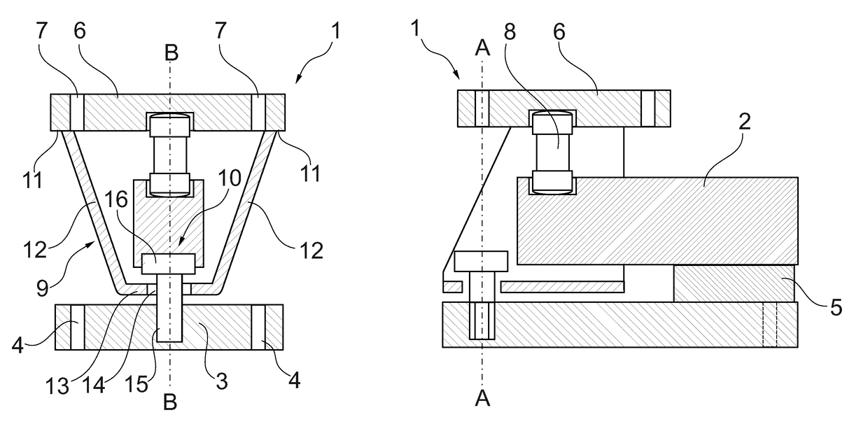
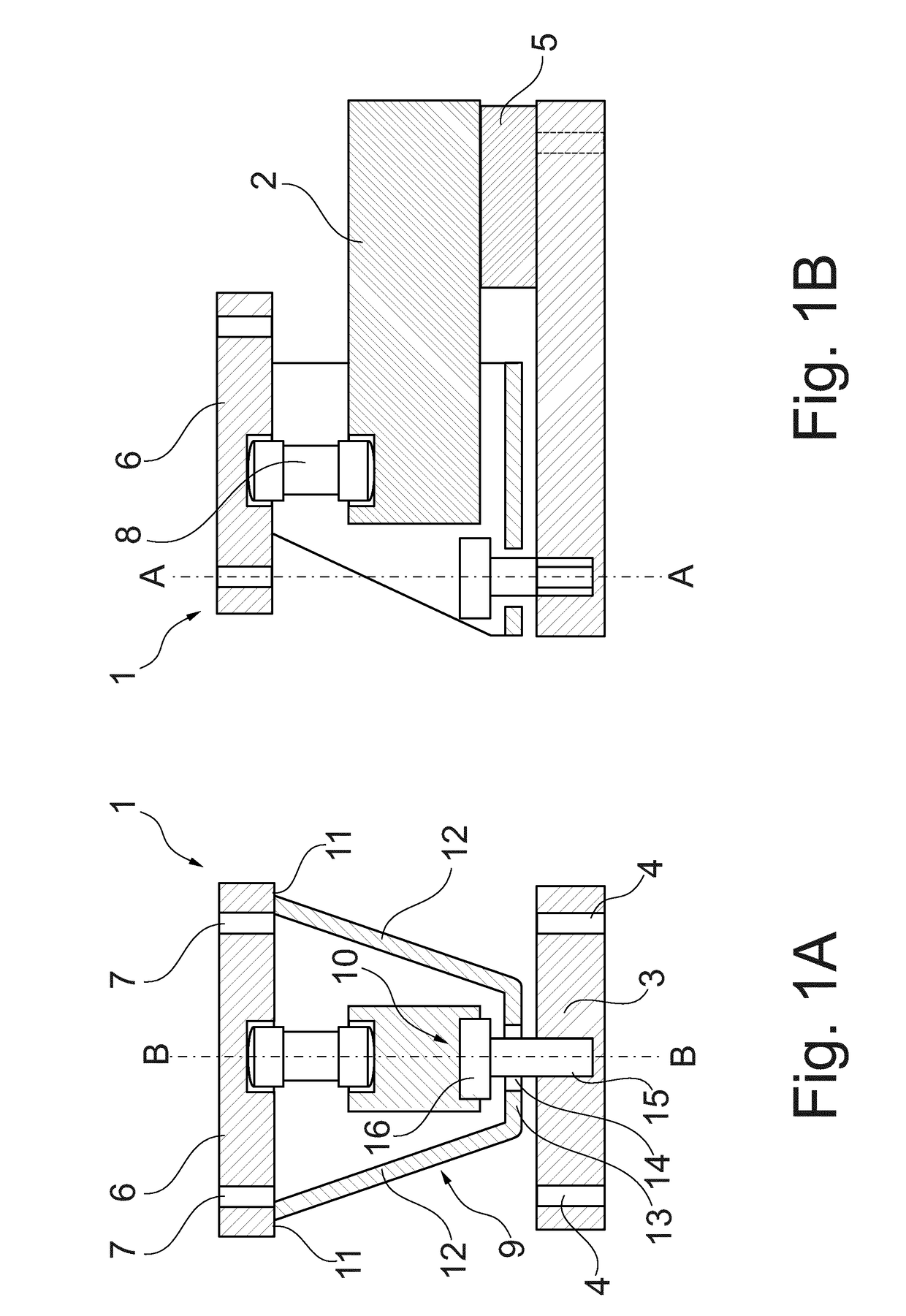
[0043]FIGS. 1A and 1B show sectional views of a weigh module 1 with a cantilever load cell 2. FIG. 1A represents a cross-section in a plane A-A as indicated in FIG. 1B, i.e. transverse to the beam direction of the cantilever load cell 2. FIG. 1B represents a longitudinal section in a plane B-B as indicated in FIG. 1A, i.e. a vertical plane bisecting the cantilever load cell 2 in the lengthwise direction. The weigh module 1 has a base plate 3 with mounting holes 4 allowing the base plate to be bolted to a foundation or support structure (not shown in the drawing). The cantilever load cell 2, outlined here in the shape of a rectangular slab which is typical of so-called shear beam load cells, is rigidly mounted on the base plate 3, vertically elevated from the latter by a spacer block 5. The weigh module 1 further has a top plate 6 with mounting holes 7 that allow the top plate 6 to be bolted to a weighing load carrier such as a weighing platform or a weighing tank (not shown in the d...


PUM


Abstract

A weigh module (1) includes a load cell (2), a base plate (3), a top plate (6), a force-transmitting member (8) serving to transmit the weighing force from the top plate (6) to the load cell (2), and movement-restricting means (9, 10) which serve to limit the horizontal floating movement of the top plate (6) relative to the base plate (3) within a confined range of free play and to transmit lateral force components directly from the top plate (6) to the base plate (3). One part of the movement-restricting means (9, 10) has the form of a channel whose top edges (11) are rigidly connected to the top plate (6) and whose flat bottom extends parallel to the base plate (3) at a clear distance from the latter. The other part of the movement-restricting means (9, 10) is a bolt whose shaft (15) is anchored in the base plate (3) and passes with all-around clearance through a passage (14) in the channel bottom (13), and whose head (16) is larger than the passage (14) and arranged above the channel bottom (13) with a vertical clearance gap from the latter.

Description

BACKGROUND OF THE INVENTION[0001]The invention concerns a weigh module for installation in a weighing scale of the kind where a weighing load carrier such as for example a platform, a tank, a hopper, or a belt conveyor is supported by a plurality of weigh modules, wherein each weigh module contains a load cell and the weight of a load on the weighing load carrier is determined by summation of the individual load cell signals.[0002]A conventional weigh module includes a base part that can be bolted to a foundation or support structure, a top part that can be bolted to the weighing load carrier, a load cell that is fastened to the base part, and a force-transmitting member which is arranged between the top part and the load cell and serves to introduce the weighing force from the top part into the load cell. The function of the weigh module is to ensure that only the substantially vertical weight force that is to be measured is received by the load cell, while laterally directed force...

Claims


Application Information

Patent Timeline
Patent Type & Authority Patents(United States)
IPC IPC(8): G01G21/23G01G23/02G01G23/00
CPCG01G23/005G01G21/23G01G23/02
Inventor PERREA, MICHAELBOGGS, ERICLEAHY, TOMPING, ZHANG
Owner METTLER TOLEDO GMBH
Why Eureka
Try Eureka