
Method of estimating equivalent radar cross section on the basis of near-field measurements

a near-field measurement and equivalent technology, applied in the field ofradar signature, can solve the problems of reducing the efficiency of absorbents, and reducing the accuracy of the calculation method

Inactive Publication Date: 2017-04-04
COMMISSARIAT A LENERGIE ATOMIQUE ET AUX ENERGIES ALTERNATIVES
View PDF11 Cites 1 Cited by
  • Summary
  • Abstract
  • Description
  • Claims
  • Application Information

AI Technical Summary

Benefits of technology

The patent describes a way to define an operator using a pseudo-inverse matrix. The operator is designed to minimize the distance between two modal values obtained through simulations. The technical effect of this invention is to provide a more accurate and efficient way to define an operator, which can be useful in various applications such as optical devices and image processing.

Problems solved by technology

These two methods do however have many limitations.
Obtaining a three-dimensional RCS by measurement is very rare and very often impossible.
Furthermore, the measurements are often affected by noises from various sources (stray echoes, instrumentation noise, etc), this problem being aggravated in the low-frequency regime (wavelength greater than or very much greater than the characteristic dimensions of the object), where the efficiency of the absorbents is less.
The bright points method does however prove to be excessively difficult to implement for complex target forms and in any event is not applicable in the low-frequency regime.
However, in low-frequency regime and / or when the antennas in question are close to the target, this approximation is no longer valid and the value of the RCS may be erroneous

Method used


Image

  • Method of estimating equivalent radar cross section on the basis of near-field measurements
  • Method of estimating equivalent radar cross section on the basis of near-field measurements
  • Method of estimating equivalent radar cross section on the basis of near-field measurements

Examples


Embodiment Construction

[0047]We will consider in the following a target, the monostatic or bistatic RCS of which is wished to be estimated, whether in high frequency or low frequency, within the meaning defined above.

[0048]In general terms, for a given frequency f the description of the bistatic RCS of the target can be expressed in the form of a matrix of size 2N×2N:

[0049]Σb=(σ11HHσ12HH…σ1⁢NHHσ11HVσ12HV…σ1⁢NHVσ21HHσ22HH…σ2⁢NHHσ21HVσ22HV…σ2⁢NHV⋮⋮⋱⋮⋮⋮⋱⋮σN⁢⁢1HHσN⁢⁢2HH…σNNHHσN⁢⁢1HVσN⁢⁢2HV…σNNHVσ11VHσ12VH…σ1⁢NVHσ11VVσ12VV…σ1⁢NVVσ21VHσ22VH…σ2⁢NVHσ21VVσ22VV…σ2⁢NVV⋮⋮⋱⋮⋮⋮⋱⋮σN⁢⁢1VHσN⁢⁢2VH…σNNVHσN⁢⁢1VVσN⁢⁢2VV…σNNVV)(3)

where each element σifπeπr is the value of the RCS observed for an incident wave of direction {right arrow over (u)}ie of polarisation πe=H or V and for a reception direction {right arrow over (u)}jr with a polarisation πr=H or V. The directions {right arrow over (u)}ie and {right arrow over (u)}jr, i, j=1, . . . , N are advantageously but not necessarily equally distributed in the solid angle 4π. For...


PUM


Abstract

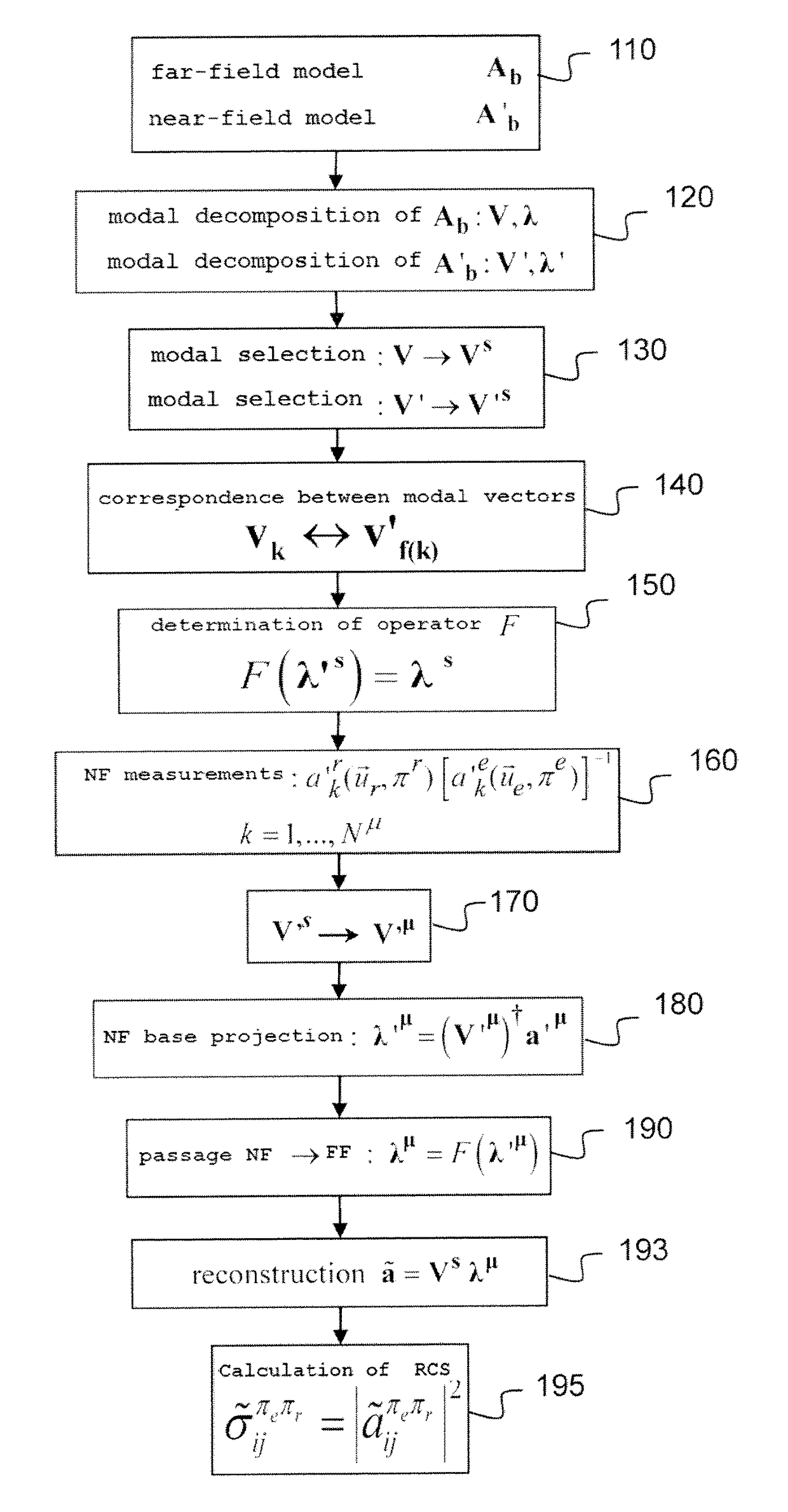
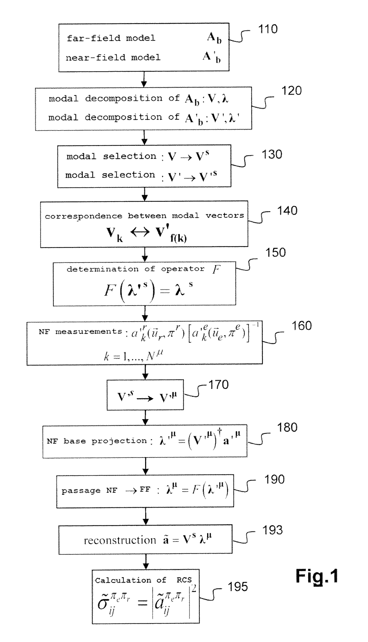
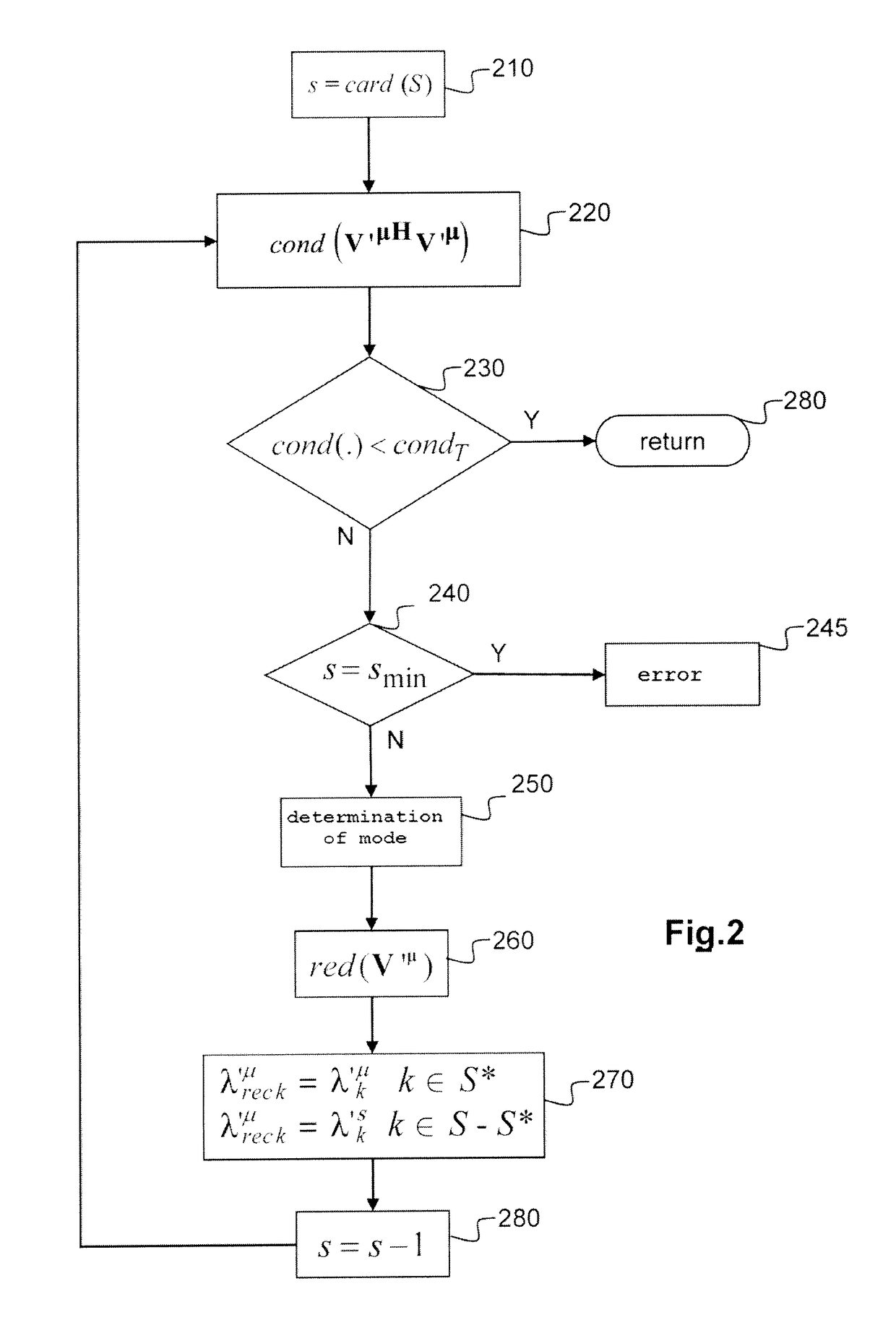
A method for estimating the equivalent radar cross section (RCS) of an object using near-field measurements. The method using a diffraction model of the object in far field and a diffraction model in near field. These models make it possible to determine respectively bases adapted to said object in far field and in near field. The measurement vector is first of all projected onto the base adapted in near field and the components obtained are transformed into components on the base in far field. The vector obtained is then returned into the analysis base of the RCS in order to provide a reconstructed vector. The components of the reconstructed vector are next used for calculating the RCS.

Description

CROSS REFERENCE TO RELATED APPLICATIONS[0001]This application is the national stage of International Application No. PCT / EP2012 / 061192, filed Jun. 13, 2012, entitled, “Method Of Estimating Equivalent Radar Cross Section On The Basis Of Near-Field Measurements,” which claims the benefit of priority of French Patent Application No. 11 55338, filed Jun. 17, 2011, the contents of which are incorporated herein by reference in its entirety.TECHNICAL FIELD[0002]The present invention concerns the field of radar signature and more particularly the determination of an equivalent radar cross section.PRIOR ART[0003]The equivalent radar cross section or RCS is a fundamental quantity that is characteristic of a target. It is used both in the military field and in the civil domain (for example for air traffic control) for the purpose of discriminating an object, typically an aircraft.[0004]The RCS of a radar target is defined conventionally from a power comparison of the wave emitted in the direct...

Claims


Application Information

Patent Timeline
Patent Type & Authority Patents(United States)
IPC IPC(8): G06F17/50G01S13/00G01S7/41
CPCG01S13/006G01S7/41G06F17/5009G06F30/20
Inventor MORVAN, SYLVAINVACUS, OLIVIER
Owner COMMISSARIAT A LENERGIE ATOMIQUE ET AUX ENERGIES ALTERNATIVES
Learn More