Zoom lens and imaging apparatus

a zoom lens and imaging apparatus technology, applied in the field of zoom lenses, can solve the problems of chromatic aberration, coma aberration, chromatic aberration, and difficulty in suppressing decentering coma, and achieve the effects of suppressing aberration variation, high optical performance, and light weigh

Active Publication Date: 2017-04-04
FUJIFILM CORP
View PDF8 Cites 0 Cited by
  • Summary
  • Abstract
  • Description
  • Claims
  • Application Information

AI Technical Summary

Benefits of technology

[0008]In a case where an image stabilization function is provided, it is important to reduce a load applied to the drive system by reducing the size and weight of the image stabilizing lens unit and reducing the amount of shift of the image stabilizing lens group. In order to address this problem, the rearmost lens group in each of Patent Documents 1 to 3 is formed by a front group having a positive refractive power, a middle group having a negative refractive power, and a rear group having a positive refractive power, and the middle group having a negative refractive power is used as the image stabilizing lens group.
[0009]By disposing the lens group having a positive refractive power in front of the image stabilizing lens group in this manner, an incident ray height on the image stabilizing lens group is reduced to achieve size reduction of the image stabilizing lens group. Further, by providing the image stabilizing lens group with a power of the opposite sign from that of the lens groups in front of and behind the image stabilizing lens group, the refractive power of the image stabilizing lens group can be increased to increase sensitivity of the image shift to shift of the image stabilizing lens group.
[0010]As described above, it is desired to achieve size reduction and weight reduction of the image stabilizing lens group and reduction of the amount of shift of the image stabilizing lens group, and it is further desired to suppress variation of chromatic aberration and suppress decentering coma along with shift of the image stabilizing lens group. Providing the image stabilizing lens group with a strong refractive power increases the sensitivity, and this allows reducing the amount of shift of the lens. In this case, however, it is difficult to suppress decentering coma, and sensitivity to assembly errors is also increased. It is therefore important to optimize the power of the image stabilizing lens group. It is also important to optimize the configuration of lens groups in front of and behind the image stabilizing lens group, which influence the refractive power (sensitivity) of the image stabilizing lens group and variation of aberrations along with shift of the lens.

Problems solved by technology

In this case, however, it is difficult to suppress decentering coma, and sensitivity to assembly errors is also increased.
In this case, however, it is difficult to suppress spherical aberration, coma aberration, and chromatic aberration.
In contrast, if the front group is provided with a weak refractive power to avoid the above described situation, it is difficult to ensure a sufficient power of the image stabilizing lens group and the power of the entire rearmost lens group becomes weak, resulting in a longer entire length of the optical system.

Method used


Image

  • Zoom lens and imaging apparatus
  • Zoom lens and imaging apparatus
  • Zoom lens and imaging apparatus

Examples


Embodiment Construction

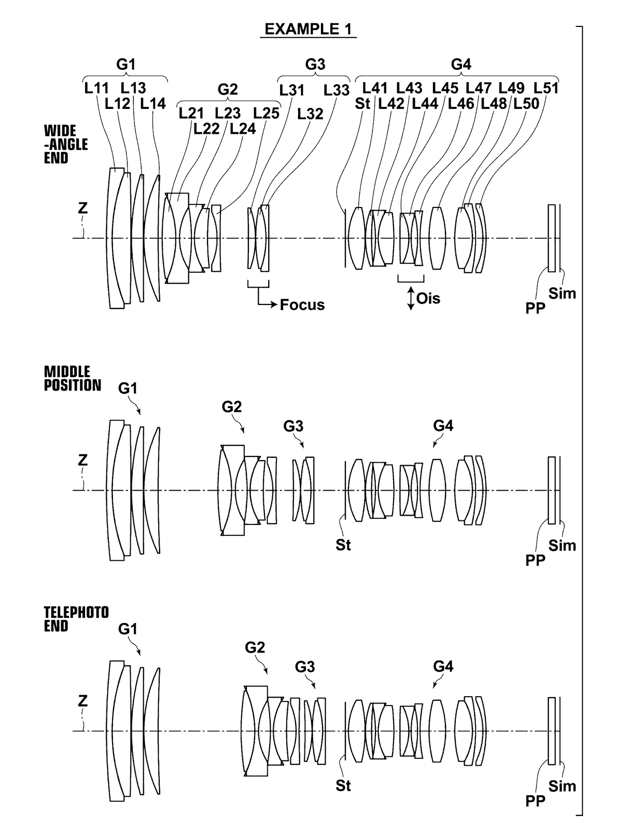
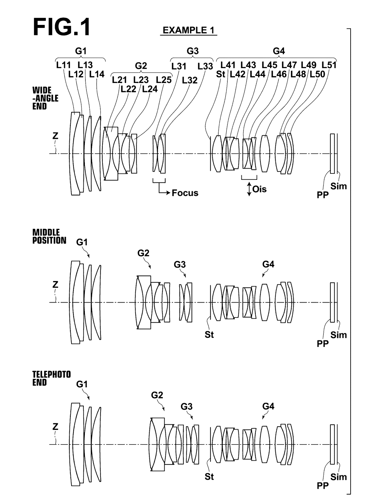
[0100]Hereinafter, an embodiment of the present invention will be described in detail with reference to the drawings. FIG. 1 is a sectional view illustrating the lens configuration of a zoom lens according to one embodiment of the invention. The configuration example shown in FIG. 1 is the same as the configuration of a zoom lens of Example 1, which will be described later. In FIG. 1, the left side is the object side and the right side is the image side. An aperture stop St shown in the drawing does not necessarily represent the size and the shape thereof, but represents the position thereof along the optical axis Z.

[0101]As shown in FIG. 1, this zoom lens consists of, in order from the object side, a first lens group G1 having a positive refractive power, a second lens group G2 having a negative refractive power, a third lens group G3 having a positive refractive power (which corresponds to an mp lens group of the invention), and a fourth lens group G4 having a positive refractive ...


PUM


Abstract

A zoom lens consists of four or five lens groups, consisting of, in order from the object side, a positive first group a negative second group, one or two middle groups including a positive mp group, and a positive rearmost group at the most image-side position of the entire system. Zooming is effected by changing all distances between the adjacent groups. The rearmost group consists of, in order from the object side, a positive front group, a negative middle group, and a positive rear group. Air spaces between the front and middle groups, and between the middle and rear groups are constant during zooming and focusing. The front group includes two positive lenses and one negative lens. Image stabilization is effected by shifting the middle group perpendicularly to the optical axis. The rear group includes one positive lens and two negative lenses. The zoom lens satisfies a given condition expression.

Description

CROSS-REFERENCE TO RELATED APPLICATIONS[0001]The present application claims priority under 35 U.S.C. §119 to Japanese Patent Application No. 2014-174108, filed on Aug. 28, 2014. The above application is hereby expressly incorporated by reference, in its entirety, into the present application.BACKGROUND OF THE INVENTION[0002]Field of the Invention[0003]The present invention relates to a zoom lens which is suitable for use with, in particular, digital cameras, lens-replaceable digital cameras, etc., and an imaging apparatus provided with the zoom lens.[0004]Description of the Related Art[0005]So-called constant aperture zoom lenses having a zoom ratio of around 2.5 to 3.0, and a constant maximum aperture of around F2.8 across the entire zoom range are known.[0006]Such a zoom lens has a four-group or five-group configuration including, for example, in order from the object side, a first lens group which has a positive refractive power and is fixed during magnification change, a second ...

Claims


Application Information

Patent Timeline
Patent Type & Authority Patents(United States)
IPC IPC(8): G02B27/64G02B15/173
CPCG02B27/646G02B15/173G02B15/144113G02B15/145121
Inventor KAWAMURA, DAIKI
Owner FUJIFILM CORP
Why Eureka
Try Eureka