
Power storage device and power storage system

a technology of power storage device and power storage system, which is applied in the direction of electrochemical generators, instruments, transportation and packaging, etc., can solve the problems that the information (data) of a usage environment and an operating condition which have been stored cannot be obtained with the power storage device, and achieves the effects of improving battery performance, long life and high capacity

Active Publication Date: 2017-04-04
SEMICON ENERGY LAB CO LTD
View PDF18 Cites 782 Cited by
  • Summary
  • Abstract
  • Description
  • Claims
  • Application Information

AI Technical Summary

Benefits of technology

[0008]An object of one embodiment of the present invention is to provide a power storage device or the like, an operating condition of which is easily analyzed.
[0013]Another object of one embodiment of the present invention is to provide a power storage system or the like, an operating condition of which is easily analyzed.
[0019]The MCU includes a volatile memory unit and a nonvolatile memory unit. A volatile memory unit includes one or more of volatile memory elements. A nonvolatile memory unit includes one or more of nonvolatile memory elements. The nonvolatile memory element has a longer data retention time than at least the volatile memory element to which power is not supplied. With use of the MCU including the nonvolatile memory unit, an intermittent operation in which operation and suspension are repeatedly performed at regular intervals can be easily achieved. Further, the nonvolatile memory unit preferably includes a memory element using an oxide semiconductor. When the memory element using an oxide semiconductor is used for the nonvolatile memory unit, power consumption of the MCU can be reduced. Note that at least part of the nonvolatile memory unit of the MCU can be used as the memory.
[0024]According to one embodiment of the present invention, a power storage device an operation condition of which is easily analyzed can be provided.

Problems solved by technology

In such a case, when the electronic device is broken or detached from the power storage device, there arises a problem in that information (data) of a usage environment and an operating condition which have been stored cannot be obtained with the power storage device alone.

Method used


Image

  • Power storage device and power storage system
  • Power storage device and power storage system
  • Power storage device and power storage system

Examples


Embodiment Construction

[0050]Hereinafter, embodiments of the present invention will be described with reference to the accompanying drawings. However, the present invention is not limited to the description below, and it is easily understood by those skilled in the art that modes and details disclosed herein can be modified in various ways without departing from the spirit and the scope of the present invention. Therefore, one embodiment of the present invention is not interpreted as being limited to the description of the embodiments described below.

[0051]Note that in structures of the present invention described below, the same portions or portions having similar functions are denoted by the same reference numerals in different drawings, and description thereof is not repeated. Further, the same hatching pattern is applied to portions having similar functions, and the portions are not especially denoted by reference numerals in some cases.

[0052]Note that in each drawing described in this specification, ...


PUM

PropertyMeasurementUnit
angleaaaaaaaaaa
angleaaaaaaaaaa
angleaaaaaaaaaa

Abstract

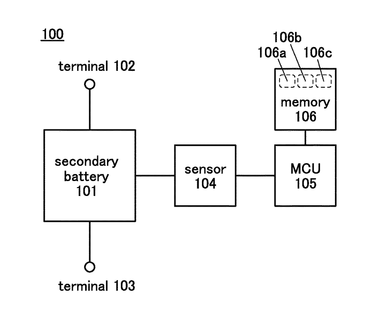
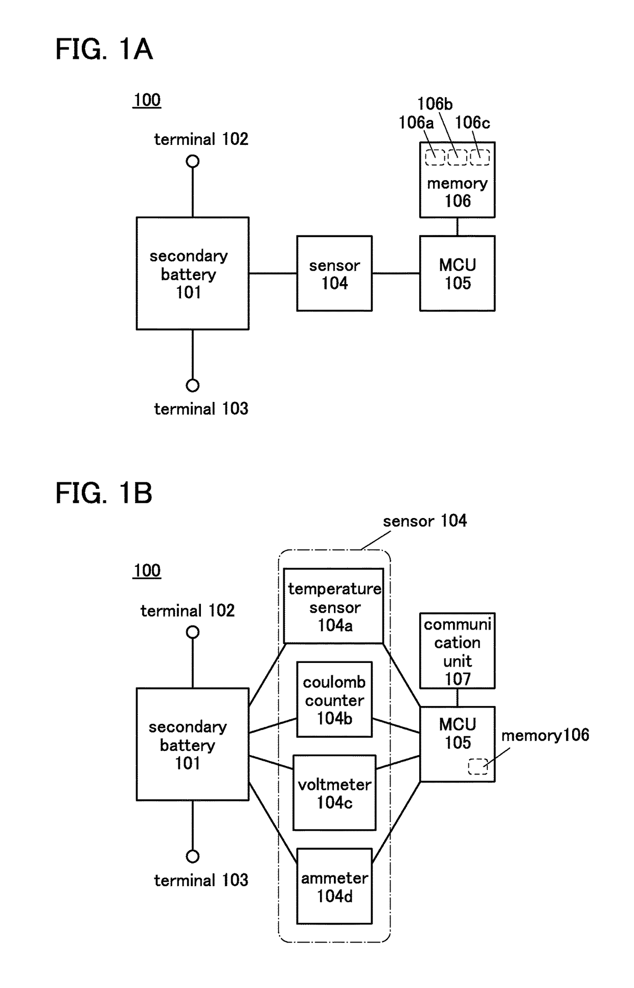
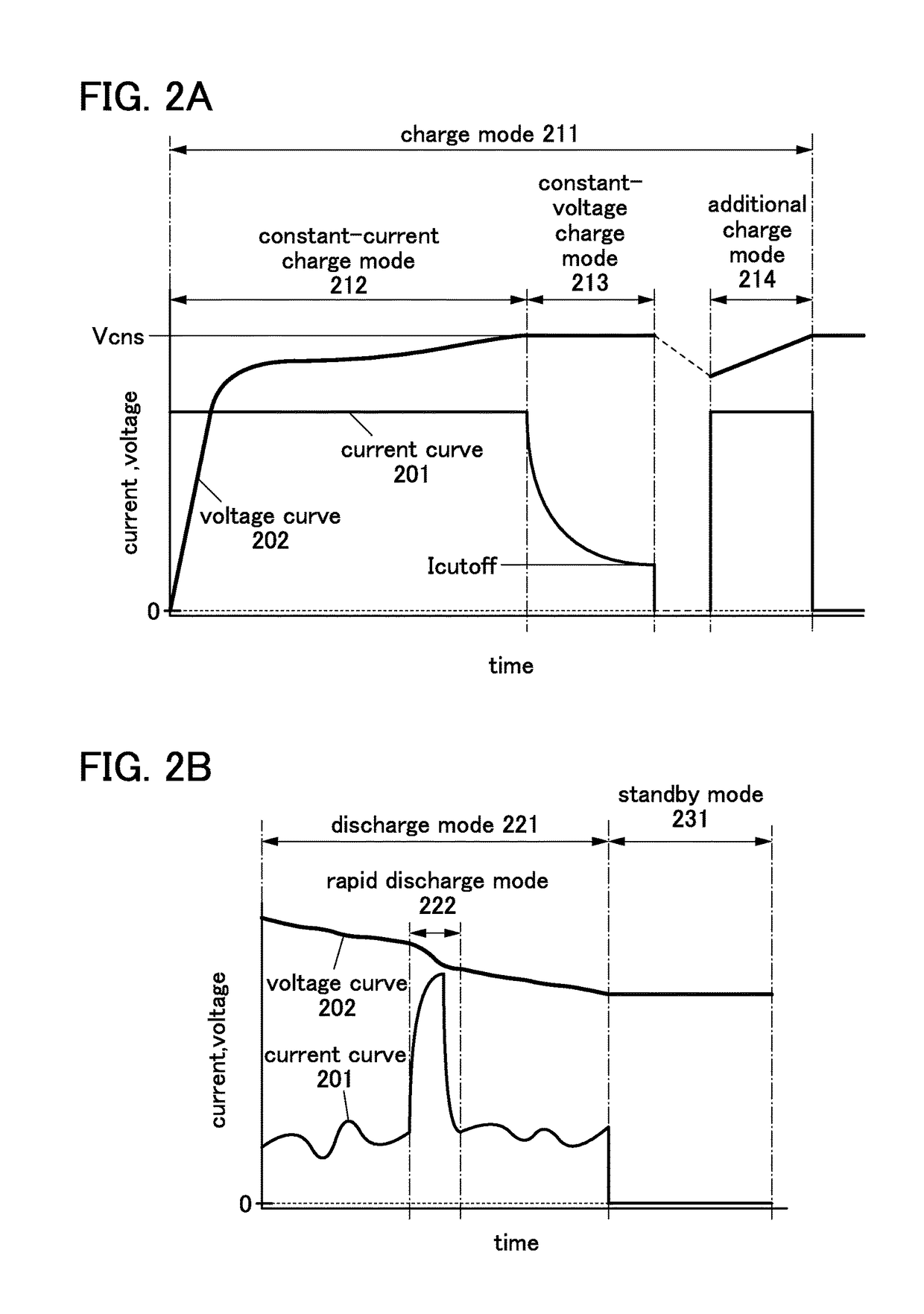
To provide a power storage device, an operation condition of which is easily analyzed. A secondary battery includes a sensor that is a measurement unit, a microcontroller unit that is a determination unit, and a memory that is a memory unit. With the sensor, conditions of the secondary battery such as the remaining battery power, the voltage, the current, and the temperature are measured. The microcontroller unit performs arithmetic processing of the measurement results and determines the operation condition of the secondary battery. Further, the microcontroller unit stores the measurement result in the memory in accordance with the operation condition of the secondary battery.

Description

TECHNICAL FIELD[0001]One embodiment of the present invention relates to an object (a product including a machine, a manufacture, and a composition of matter) and a method (a process including a simple method and a production method). In particular, one embodiment of the present invention relates to a power storage system, a power storage device, a semiconductor device, or other electric devices and a driving method thereof or a manufacturing method thereof.[0002]Note that the power storage device indicates all elements and devices which have a function of storing power. In this specification, a semiconductor device means all types of devices that can function by utilizing semiconductor characteristics, and a transistor, a semiconductor circuit, a memory device, an imaging device, a display device, an electro-optical device, an electronic device, and the like are all semiconductor devices. Further, a power storage device can also function as a semiconductor device.BACKGROUND ART[0003...

Claims


Application Information

Patent Timeline
Patent Type & Authority Patents(United States)
IPC IPC(8): H02J7/00H01M10/48G01R31/36
CPCH01M10/48H01M10/486G01R31/3606G01R31/382Y02E60/10
Inventor TAKAHASHI, MINORUTAKAHASHI, KEIKOYAMA, JUNMOMO, JUNPEIMORIWAKA, TAMAE
Owner SEMICON ENERGY LAB CO LTD
Learn More