Rotor for a turbomachine

a turbomachine and rotor technology, applied in machines/engines, couplings, liquid fuel engines, etc., can solve problems such as failure of adhesives, and achieve good coverag

Active Publication Date: 2017-04-18
DYSON TECH LTD +1
View PDF53 Cites 5 Cited by
  • Summary
  • Abstract
  • Description
  • Claims
  • Application Information

AI Technical Summary

Benefits of technology

[0005]By employing a part interference fit and part adhesive join to secure the impeller to the shaft, torque transmission between the impeller and the shaft may be achieved without the need for an interference fit that exceeds the yield point of the impeller or requires an excessive press force. In particular, the adhesive between the shaft and the counterbore may be of sufficient strength to ensure that the required torque is transmitted between the impeller and the shaft. The interference fit may then be employed primarily to maintain alignment between the impeller and the shaft. Since the interference fit is employed primarily for alignment rather than torque transmission, an interference fit may be employed that does not require an excessive press force and does not exceed the yield point of the impeller.
[0006]The impeller may comprise a hub, a plurality of blades provided on the hub, and a boss that extends axially from the hub. The bore may then be formed in the hub and the counterbore may be formed in the boss. As the rotor rotates, the impeller is stressed radially, which causes the diameters of the bore and the counterbore to expand. The majority of the mass of the impeller typically resides in the hub and blades. As a result, radial expansion will be greatest at the hub. In contrast, the boss is typically lighter and is therefore subject to less radial expansion. By locating the counterbore in the boss, excessive peel stress of the adhesive may be avoided.
[0009]The impeller may be formed of plastic, which has the advantages of weight and cost over many other materials. Being formed of plastic, the yield point of the impeller may be relatively low. By employing a part interference fit and part adhesive join, torque transmission between the impeller and the shaft may be achieved without the need for an interference fit that would otherwise exceed the yield point of the impeller.
[0013]The adhesive may be introduced into the counterbore such that the adhesive creates a wet seal around the shaft. Consequently, as the shaft is inserted into the counterbore, air occlusion is avoided and a continuous layer of adhesive is formed between the shaft and the counterbore. A relatively strong adhesive bond is then formed between the shaft and the impeller.

Problems solved by technology

However, since radial expansion is likely to be greatest at the hub, the resulting peel stress may result in failure of the adhesive.

Method used


Image

  • Rotor for a turbomachine
  • Rotor for a turbomachine
  • Rotor for a turbomachine

Examples


Embodiment Construction

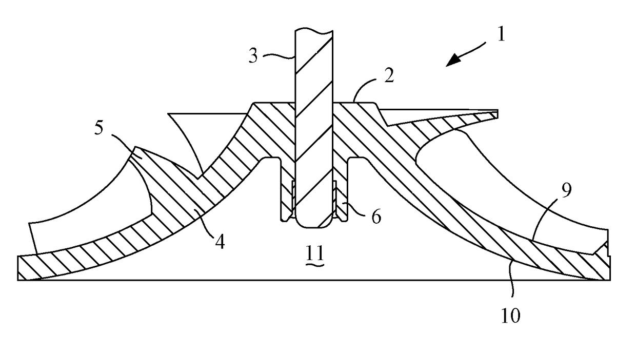
[0020]The rotor 1 of FIGS. 1 and 2 comprises an impeller 2 secured to a shaft 3.

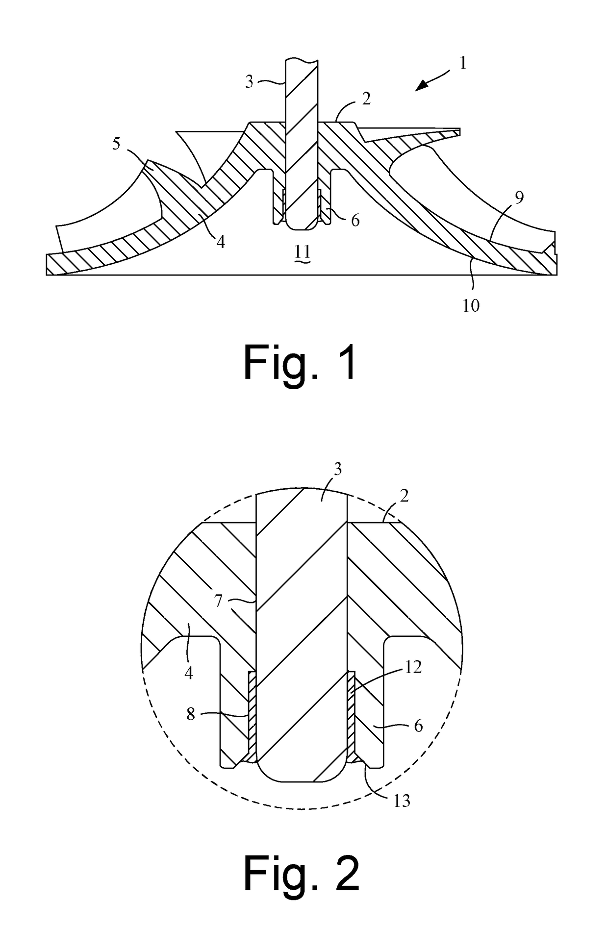
[0021]The impeller 2 comprises a hub 4, a plurality of blades 5, a boss 6, a bore 7 and a counterbore 8.

[0022]The hub 4 has an aerodynamic upper surface 9 on which the blades 5 are provided, and a lower surface 10 that defines a recess 11 in the underside of the hub 4.

[0023]The boss 6 is cylindrical in shape and extends axially from the center of the hub 4. More specifically, the boss 6 extends downward from the lower surface 10 of the hub 4 and into the recess 11.

[0024]The bore 7 extends axially through the center of the hub 4 and into an upper part of the boss 6. The counterbore 8 extends axially through the lower part of the boss 6. The bore 7 and counterbore 8 thus provide an axial conduit through the impeller 2.

[0025]The shaft 3 is received within the bore 7 and the counterbore 8. The bore 7 and counterbore 8 are sized such that the shaft 3 forms an interference fit with the bore 7 and a clearance f...


PUM

PropertyMeasurementUnit
radial stressaaaaaaaaaa
speedsaaaaaaaaaa
yield pointaaaaaaaaaa

Abstract

A rotor that includes an impeller secured to a shaft. The impeller has a bore and a counterbore. The shaft forms an interference fit with the bore and is adhered to the counterbore. A method of manufacturing the rotor is also described.

Description

REFERENCE TO RELATED APPLICATIONS[0001]This application claims the priority of United Kingdom Application No. 1102132.6, filed Feb. 8, 2011, the entire contents of which are incorporated herein by reference.FIELD OF THE INVENTION[0002]The present invention relates to a rotor for a turbomachine.BACKGROUND OF THE INVENTION[0003]The rotor of a turbomachine typically comprises an impeller secured to a shaft. The impeller may be secured to the shaft by interference fit, which provides a cost-effective means of securement. As the rotor rotates, radial stresses cause the bore of the impeller to expand. As a result, the interference fit between the impeller and shaft decreases. At relatively high speeds, the expansion of the bore may be such that the interference fit is no longer able to transmit the required torque between the shaft and the impeller. In order to avoid this situation, the interference fit between the impeller and the shaft, when stationary, may be increased. However, the re...

Claims


Application Information

Patent Timeline
Patent Type & Authority Patents(United States)
IPC IPC(8): F04D29/02F04D29/28F04D29/26F04D29/20
CPCF04D29/20F04D29/02F04D29/026F04D29/263F04D29/28F05D2300/43Y10T29/49316Y10T29/49321F16D1/068F04D29/26
Inventor DYMOND, NIGEL YOUATTIONS, DAVID
Owner DYSON TECH LTD
Why Eureka
Try Eureka