Antenna array

a technology of antenna array and array structure, applied in the field of antenna array, can solve the problems of increasing the size of the antenna array and limited the maximum directivity of this type of antenna array structure, and achieve the effect of reducing compactness and enhancing directivity

Active Publication Date: 2017-04-25
COMMISSARIAT A LENERGIE ATOMIQUE ET AUX ENERGIES ALTERNATIVES
View PDF7 Cites 2 Cited by
  • Summary
  • Abstract
  • Description
  • Claims
  • Application Information

AI Technical Summary

Benefits of technology

[0009]There is therefore a need for an antenna array having enhanced directivity with reduced compactness.

Problems solved by technology

However, these solutions greatly increase the size of the antenna array.
However, the level of maximum directivity achievable with this type of antenna array structure is limited by the directivity of the ideal Huygens source, which is 4.7 dBi.

Method used


Image

  • Antenna array
  • Antenna array
  • Antenna array

Examples


Embodiment Construction

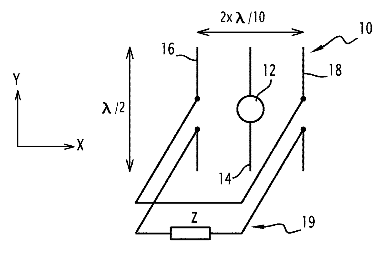
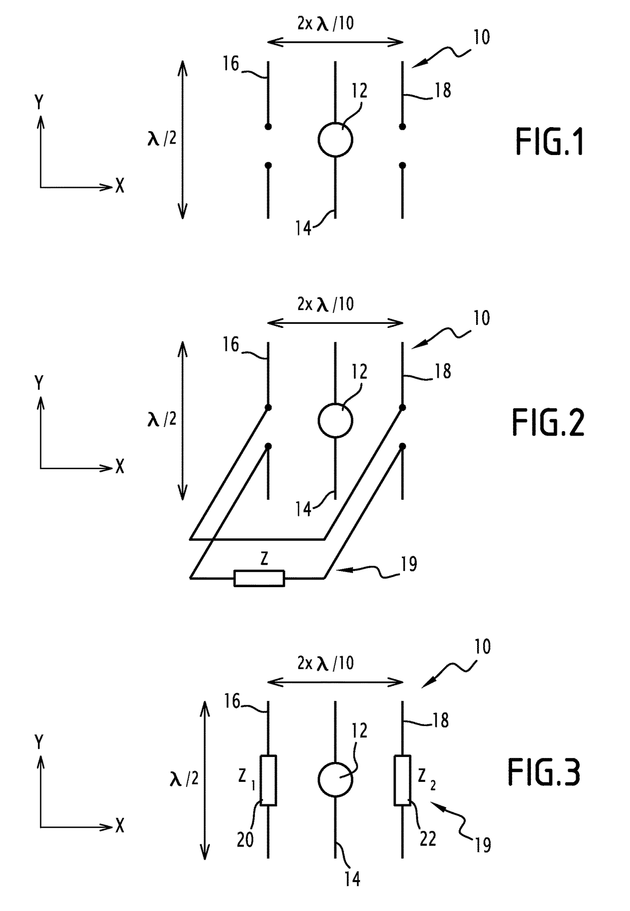
[0021]An antenna array 10 has been provided as shown in a generic fashion in FIG. 1 and in the two embodiments in FIGS. 2 and 3. An antenna array generally comprises at least one primary antenna and one secondary antenna. Each of the antennas belonging to the antenna array comprises one or more radiating parts. The radiating parts of each separate antenna are physically separated. The term “physically separated”, is understood to mean that there is no physical contact between two radiating parts belonging to two distinct and separate antennas.

[0022]For the rest of the description, two axes X and Y contained in the FIGS. 1 to 3 have been defined. The axis X is perpendicular to the axis Y. A direction parallel to the axis X is referred to as a longitudinal direction and a direction parallel to the axis Y is referred to as a transverse direction.

[0023]The antenna array 10 comprises a source 12, a first antenna 14, a second antenna 16, a third antenna 18 and a circuit 19 (not shown in F...


PUM


Abstract

This antenna array includes at least one primary antenna, at least one secondary antenna and at least one load coupled to a secondary antenna. The load includes two separate components, a first component being a resistor and a second component being selected from an inductor or a capacitor. The antenna array can include one or more of the following characteristic features, taken into consideration individually or in accordance with any technically possible combinations: the first component has negative resistance; the second component has negative inductance or a negative capacitance; at least one load has an adjustable impedance. The antenna array may be used in a system, such as a vehicle, a terminal, a mobile telephone, a wireless network access point, a base station, or a radio frequency excitation probe.

Description

FIELD OF THE INVENTION[0001]The present invention relates to a method for determining an antenna array. The present invention also relates to an antenna array.BACKGROUND OF THE INVENTION[0002]The invention is applicable to the field of antenna arrays. For a number of applications, a directional radiation pattern is desirable. By way of an example, a focused radiation in a preferred direction is required for detection and communication with a target. Avoiding electromagnetic pollution outside of the useful zones is another example of an application involving a relatively directional radiation pattern.[0003]In order to increase the directivity of an antenna array, it is a known technique from the state of the art to use reflectors such as parabolic reflectors, to network antennas or to combine coupled antennas as in the case of antennas like the Yagi-Uda.[0004]However, these solutions greatly increase the size of the antenna array. Indeed, the directivity of a reflector antenna is typ...

Claims


Application Information

Patent Timeline
Patent Type & Authority Patents(United States)
IPC IPC(8): H01Q9/00H01Q21/00H01Q1/48
CPCH01Q21/00H01Q1/48
Inventor BELMKADDEM, KAWTARRUDANT, LIONEL
Owner COMMISSARIAT A LENERGIE ATOMIQUE ET AUX ENERGIES ALTERNATIVES
Why Eureka
Try Eureka