Vehicle seat

a technology for vehicles and seats, applied in the field of vehicles, can solve the problems of difficult to improve seating comfort and limit the adjustment of seating comfort, and achieve the effects of reducing density, reducing thickness, and reducing weigh

Inactive Publication Date: 2017-05-02
TOYOTA BOSHOKU KK
View PDF26 Cites 29 Cited by
  • Summary
  • Abstract
  • Description
  • Claims
  • Application Information

AI Technical Summary

Benefits of technology

[0009]According to the above aspect, the density and the thickness of the skin are partially changed to make the bending easiness of the skin partially different. Thus, the seating comfort may be adjusted with the control of deformation of the supporting surface.
[0011]In a part of the supporting surface constituted by the second region of the skin that more hardly bends due to its higher density and greater thickness, the load from the seated occupant is dispersedly applied to the seat pad. Therefore, the surface shape of the supporting surface hardly changes. However, the first regions of the skin that easily bend due to their lower density and smaller thickness are arranged between the main portion and the side support portions. As a result, the supporting surface easily locally bends in the portions. Therefore, the region in which the surface shape hardly changes is divided in the width direction, and the main portion is greatly displaceable in a direction in which it receives the load while maintaining the surface shape. Accordingly, the seated occupant easily sinks into the supporting surface.
[0012]The supporting surface may be a backrest surface of a seat back, and the first regions may be arranged at positions at which blade bones of the seated occupant are supported. In this case, the seated occupant easily sinks into the backrest surface at the height of the blade bones around which the seated occupant is likely to swing when the vehicle turns. Therefore, the vehicle seat can improve its holding performance.
[0013]The first regions may extend from a height at which the blade bones of the seated occupant are supported to a height at which a lumbar of the seated occupant is supported so as to become gradually narrower toward a lower side of the vehicle seat. In this case, the lumbar is most unlikely to sink into the backrest surface, and the sinking degree of the main portion becomes greater toward the height of the blade bones. Therefore, the supporting surface wraps around the blade bones and the surrounding areas (around the shoulders) while firmly holding the lumbar of the seated occupant. As a result, the seating comfort can be improved.
[0014]The supporting surface may be a seating surface of a seat cushion, the first region may be arranged at a position at which a pelvis of the seated occupant is supported, and the second region may be arranged ahead of the first region. In this case, the seating surface easily deforms at its part beneath the pelvis of the seated occupant at which the first region of the skin is arranged, and thus the seated occupant easily sinks into the seating surface. While, since the load is dispersedly applied to the seat cushion in the second region ahead of the first region, the seated occupant more hardly sinks into the seating surface in the second region. Therefore, the seating surface receives the pelvis of the seated occupant in the second region that more hardly sinks when the seated occupant receives forward acceleration, whereby the seated occupant can be prevented from relatively moving to the front side.
[0015]The skin may have a third region that is arranged adjacent to and ahead of the second region and extends to a front end of the seating surface, and the third region may be lower in density and thinner than the second region. In this case, the seating surface easily deforms at the front end portion at which the third region of the skin is arranged, and thus occupant's feet motions are not easily hindered. Therefore, the seated occupant easily performs a pedaling operation in, for example, the driver's seat or the like of the vehicle while being prevented from relatively moving to the front side.

Problems solved by technology

However, there is a limitation on adjusting the seating comfort only by changing the properties of the seat pad.
Particularly, when the entire seat pad is made thinner for the purpose of, for example, reduction in the weight of the seat, it is difficult to improve the seating comfort only by changing the properties of the seat pad.

Method used


Image

  • Vehicle seat
  • Vehicle seat
  • Vehicle seat

Examples


first embodiment

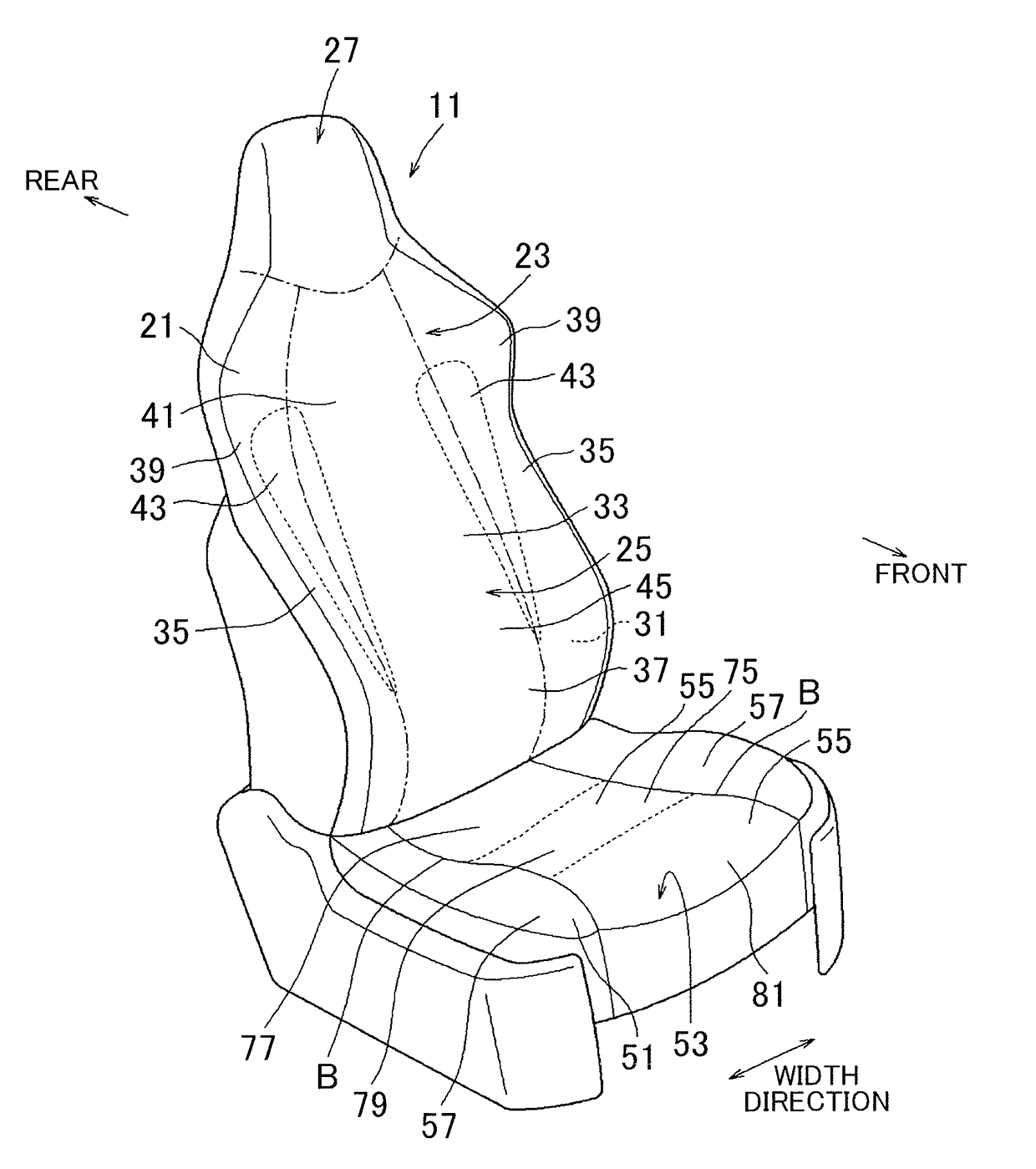
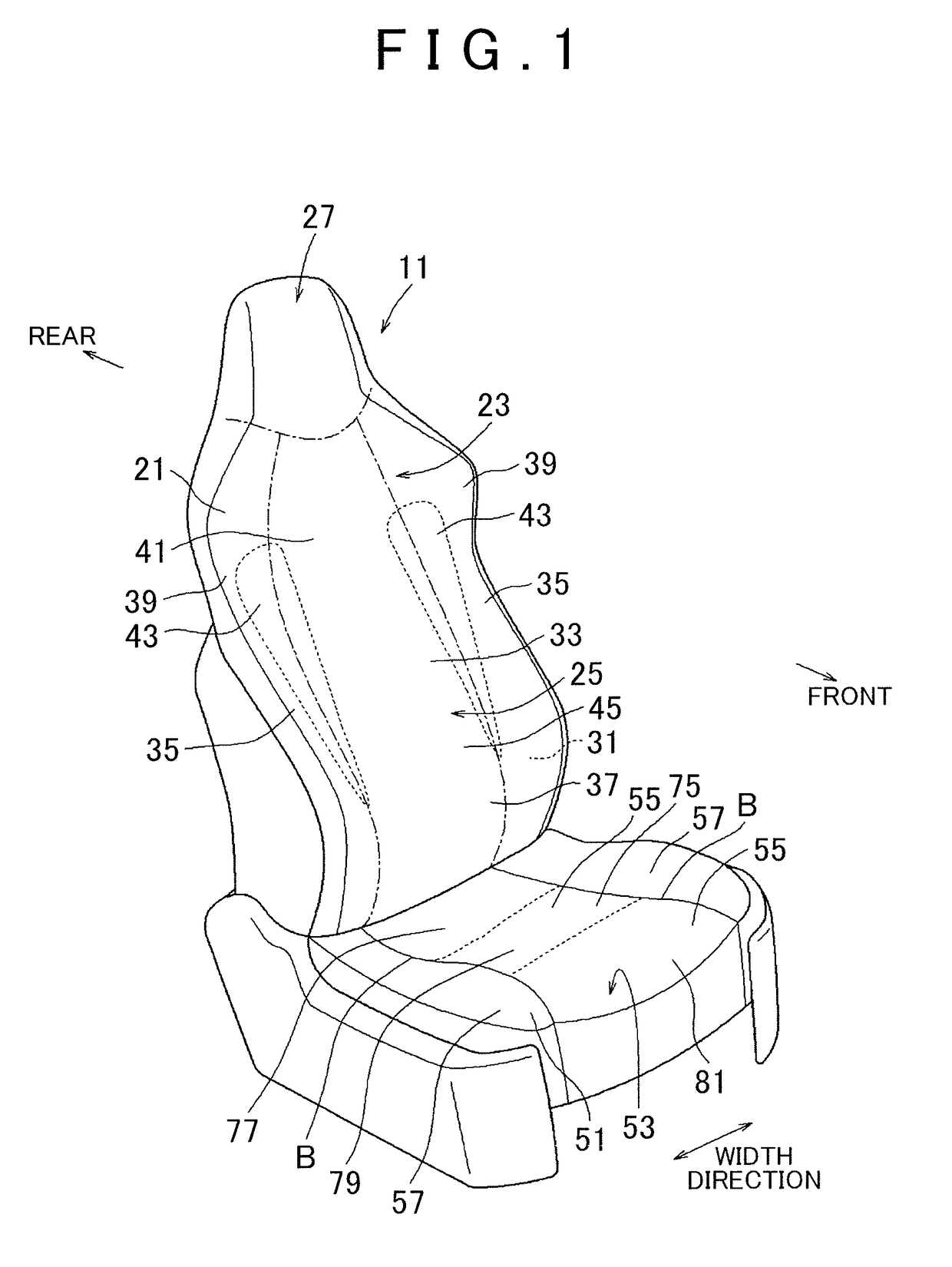
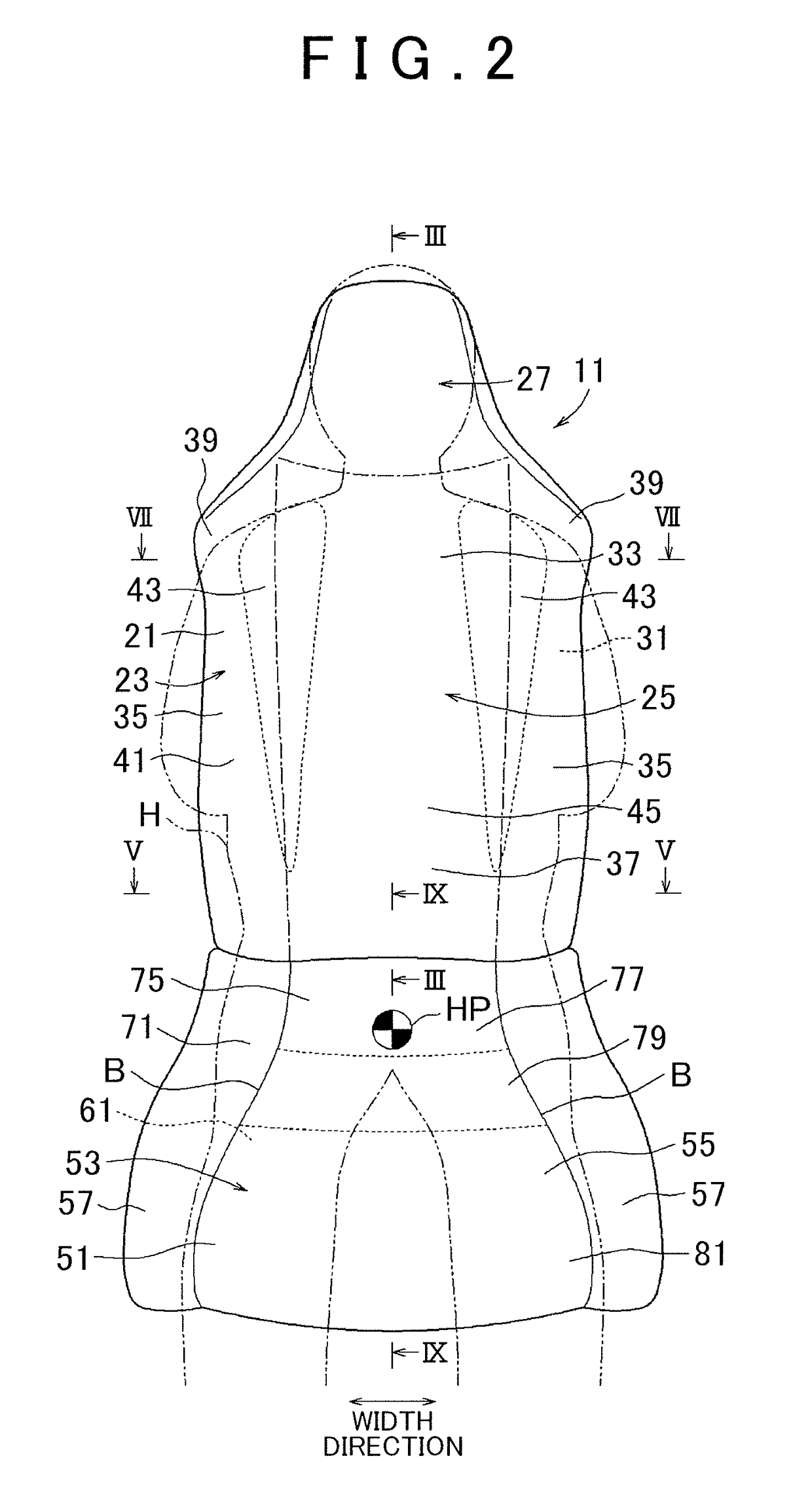
[0029]First, the configuration of the seat back 21 will be described. The seat back 21 has, as a supporting surface 23 that supports a seated occupant H, a backrest surface 25 that supports the back, and has a headrest portion 27 integrally formed on its upper side. Note that in FIGS. 1 and 2, the distinction between the backrest surface 25 and the headrest portion 27 of the supporting surface 23 is shown by a dashed line for convenience. As shown in FIG. 3, the supporting surface 23 is formed by a seat pad 31. The seat pad 31 is covered with a shell 29, which is a rigid body, at its rear surface and held by the shell 29. The seat pad 31 is made of urethane foam and has uniform hardness. The front surface of the seat pad 31 that forms the supporting surface 23 is covered with a skin 41 along its surface shape.

[0030]As shown in FIGS. 1 and 2, the backrest surface 25 of the seat back 21 has a main portion 33 that supports the back of the seated occupant H at the intermediate portion ...

second embodiment

[0039]First, the configuration of the seat cushion 51 will be described. As shown in FIGS. 1 and 2, the seat cushion 51 has, as the supporting surface 23 that supports the seated occupant H, a seating surface 53 on which the seated occupant H sits down. The seating surface 53 is formed by a cushion pad 61. The cushion pad 61 functions as a seat pad. As shown in FIG. 9, the cushion pad 61 is put on a frame-shaped cushion frame (not shown). The upper surface of the cushion pad 61 forms the seating surface 53, and the lower surface thereof is elastically supported by S-shaped springs (not shown) laid over the cushion frame. The cushion pad 61 is made of urethane foam. The cushion pad 61 is covered with a cushion cover 71 arranged along the front surface of the seat cushion 51. The shape of the upper surface of the cushion pad 61, i.e., the shape of the seating surface 53 is substantially flat at the intermediate portion in the width direction of the cushion pad 61. The upper surface o...


PUM


Abstract

A vehicle seat includes: a seat pad that forms a supporting surface that supports a seated occupant; and a skin that is made of a knitted fabric or a woven fabric and covers the seat pad. The skin has a first region and a second region arranged adjacent to each other on the supporting surface, and the first region is lower in density and thinner than the second region.

Description

INCORPORATION BY REFERENCE[0001]The disclosure of Japanese Patent Application No. 2014-104121 filed on May 20, 2014 including the specification, drawings and abstract is incorporated herein by reference in its entirety.BACKGROUND OF THE INVENTION[0002]1. Field of the Invention[0003]The invention relates to a vehicle seat.[0004]2. Description of Related Art[0005]Up until now, vehicle seats in which the hardness of a seat pad is partially changed to improve the seating comfort have been available. Japanese Patent Application Publication No. 2000-189289 (JP 2000-189289 A) describes technology for partially changing not only the hardness but also the modulus of repulsion elasticity of a seat pad in a seat cushion to improve the seating comfort. Specifically, in the seat cushion described in JP 2000-189289 A, both side portions in its width direction are set to be higher in hardness and lower in the modulus of repulsion elasticity than the intermediate portion. According to thus configur...

Claims


Application Information

Patent Timeline
Patent Type & Authority Patents(United States)
IPC IPC(8): A47C7/02B60N2/68B60N2/64B61D33/00B60N2/70B60N2/58A47C7/18A47C7/24B64D11/06
CPCB60N2/646B60N2/58B60N2/643B60N2/68A47C7/18A47C7/24B60N2/5891B60N2/70B61D33/0035B64D11/0647
Inventor ABE, SAKINOMATSUDA, MOTOHIROASANO, HISATOMO
Owner TOYOTA BOSHOKU KK
Why Eureka
Try Eureka