Optical transmitter and DC bias control method

a technology of optical transmitter and control method, which is applied in the direction of optics, electrical equipment, instruments, etc., can solve the problems of complicated configuration of optical transmitter, and achieve the effect of stably realizing

Active Publication Date: 2017-05-02
MITSUBISHI ELECTRIC CORP
View PDF11 Cites 8 Cited by
  • Summary
  • Abstract
  • Description
  • Claims
  • Application Information

AI Technical Summary

Benefits of technology

[0019]According to one embodiment of the present invention, the optical transmitter for modulating the light from the light source to generate the optical transmission signal with use of the data sequence as the electric signal includes: the mapping section for mapping the data sequence to be converted into the multi-level data based on the modulation multi-level degree information indicating the multi-level degree of the modulation; the D / A converter for converting the multi-level data output from the mapping section into the analog signal; the optical modulator to be driven based on the analog signal output from the D / A converter, for modulating the light from the light source; and the bias control section for setting the control polarity of the DC bias control of the optical modulator based on the modulation multi-level degree information. Thus, the plurality of multi-level modulation schemes can be stably realized with the simple modulator configuration.

Problems solved by technology

As a result, there is a problem in that the configuration of the optical transmitter is complicated.

Method used


Image

  • Optical transmitter and DC bias control method
  • Optical transmitter and DC bias control method
  • Optical transmitter and DC bias control method

Examples


first embodiment

[0026

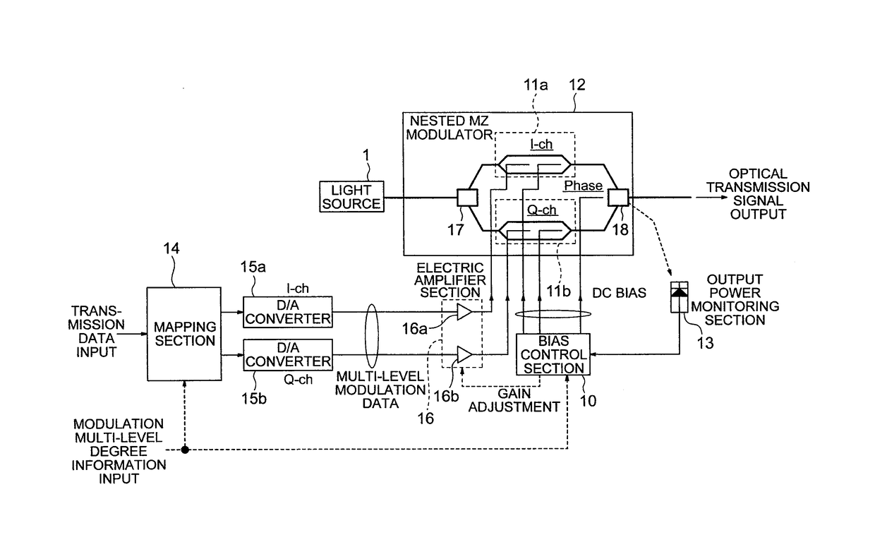
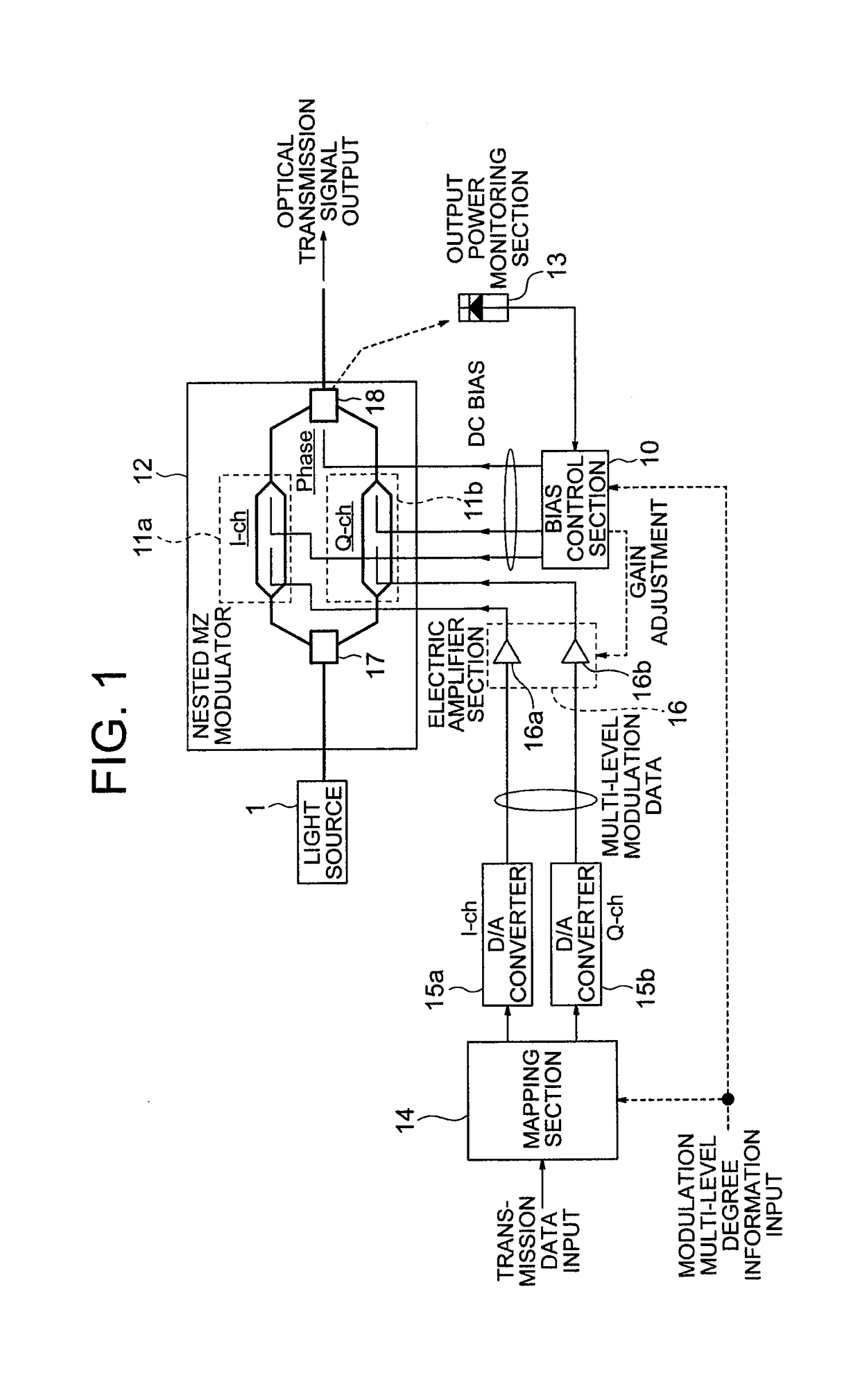
[0027]FIG. 1 is a configuration diagram illustrating an optical transmitter according to a first embodiment of the present invention. The optical transmitter uses a data sequence (binary data) as an electric signal to modulate light from a light source with an optical modulator, to thereby generate an optical transmission signal having an arbitrary optical waveform.

[0028]In FIG. 1, the optical transmitter includes a light source 1, a bias control section 10, a nested MZ modulator 12 (optical modulator), an output power monitoring section 13, a mapping section 14, D / A converters 15a and 15b, and an electric amplifier section 16. Further, the electric amplifier section 16 includes two electric amplifiers 16a and 16b.

[0029]The nested MZ modulator 12 includes two Mach-Zehnder modulators (hereinafter referred to as “MZ modulators”) 11a and 11b, an optical branch section 17, and an optical multiplexer section 18.

[0030]In this embodiment, a dual-parallel Mach-Zehnder modulator (DP-MZ...


PUM


Abstract

An optical transmitter for modulating light from a light source to generate an optical transmission signal with use of a data sequence as an electric signal, the optical transmitter including: a mapping section for mapping the data sequence to be converted into multi-level data based on modulation multi-level degree information indicating multi-level degree of the modulation; a D / A converter for converting the multi-level data output from the mapping section into an analog signal; an optical modulator to be driven based on the analog signal output from the D / A converter, for modulating the light from the light source; and a bias control section for setting control polarity of DC bias control of the optical modulator based on the modulation multi-level degree information.

Description

TECHNICAL FIELD[0001]The present invention relates to an optical transmitter and a DC bias control method, and more particularly, to an optical transmitter and a DC bias control method for stably generating a plurality of multi-level modulated optical signals.BACKGROUND ART[0002]Multi-level modulation has been actively applied to an optical communication system in view of enhancement in capacity and improvement in frequency use efficiency. So as to realize a more flexible system configuration, there is disclosed a transmission method involving changing a modulation scheme (transmission rate or transmission bandwidth) in an adaptive manner with use of multi-level modulation (see, for example, Non Patent Literature 1). In Non Patent Literature 1, each Mach-Zehnder (MZ) modulator is driven by binary signals. Thus, a normal binary modulation scheme can be used for bias control of each MZ modulator. In this case, however, the number of modulators needs to be increased as the multi-level ...

Claims


Application Information

Patent Timeline
Patent Type & Authority Patents(United States)
IPC IPC(8): H04B10/564H04B10/516
CPCH04B10/564H04B10/516G02F1/0123G02F1/035H04B10/50575H04B10/541
Inventor SUGIHARA, TAKASHIYOSHIDA, TSUYOSHI
Owner MITSUBISHI ELECTRIC CORP
Why Eureka
Try Eureka