Power transmitting device

a transmission device and power technology, applied in the direction of mechanical control devices, gearing, instruments, etc., can solve the problems of increasing the size of the power transmission device inclusive of the separate member, the difficulty of installing adjacent the input shaft, and the gear changer disposed between, so as to improve the maintenance of the shifter mechanism, improve the maintenance effect, and increase the capacity of the pump without increasing the size of the engin

a transmission device and power technology, applied in the direction of mechanical control devices, gearing, instruments, etc., can solve the problems of increasing the size of the power transmission device inclusive of the separate member, the difficulty of installing adjacent the input shaft, and the gear changer disposed between, so as to improve the maintenance of the shifter mechanism, improve the maintenance effect, and increase the capacity of the pump without increasing the size of the engin

US9644736B2Active Publication Date: 2017-05-09KAWASAKI MOTORS LTD

Image

  • Power transmitting device
  • Power transmitting device
  • Power transmitting device

Examples


Embodiment Construction

[0026]Hereinafter, a preferred embodiment of the present invention will be described in detail with particular reference to the accompanying drawings. It is to be noted that the terms “left” and “right” are used to denote opposite positions or directions, respectively, relative to a motorcycle rider or motorist then occupying a motorcycle rider's seat and looking forwards in a direction parallel to the longitudinal sense of the motorcycle.

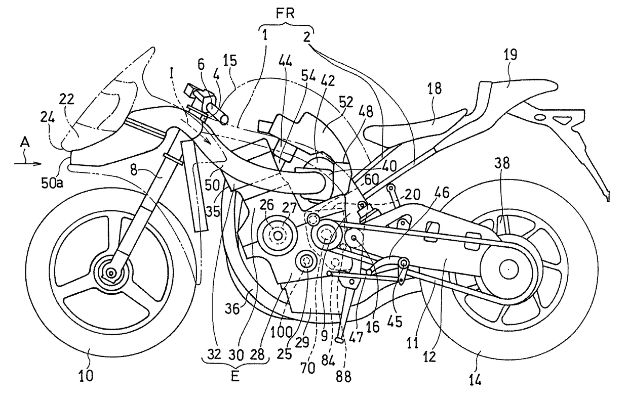
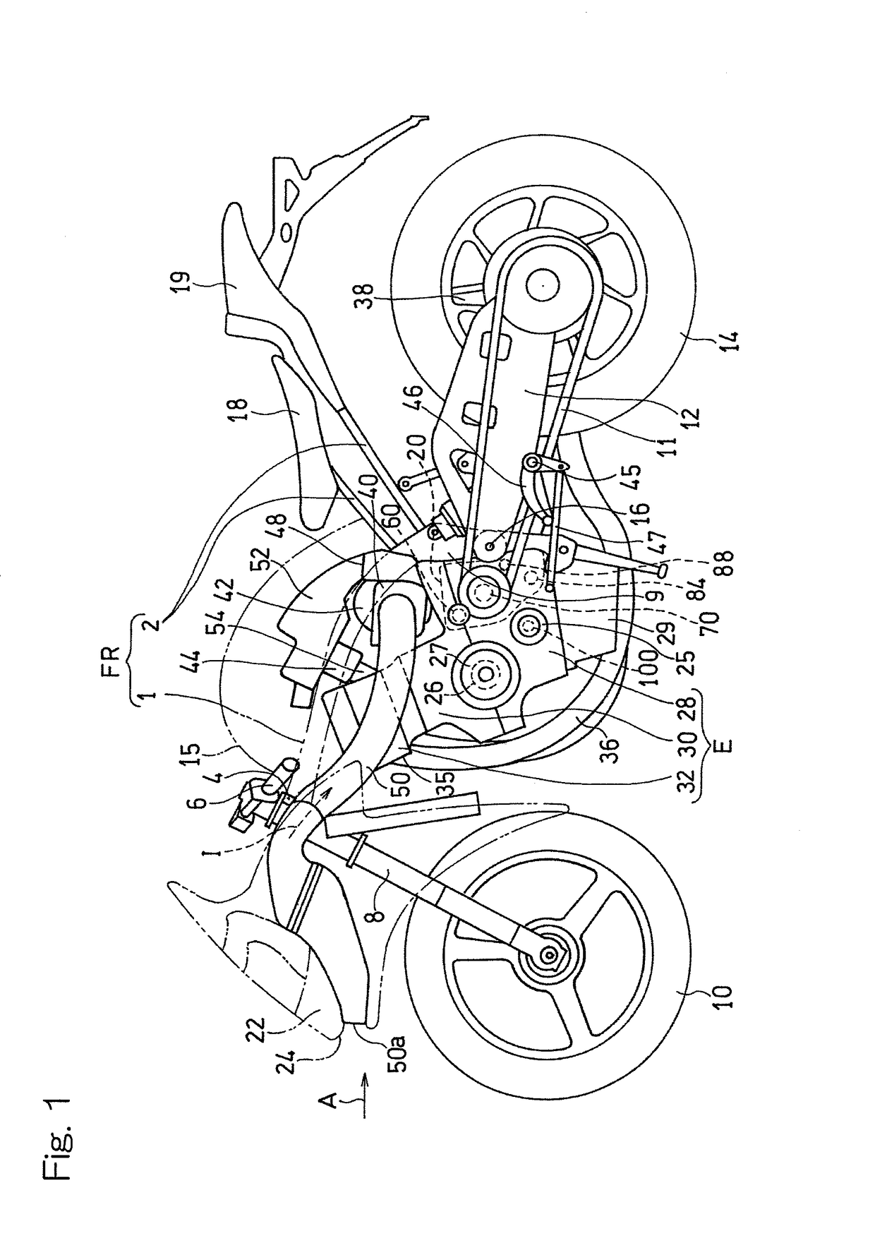
[0027]FIG. 1 is a side view showing a motorcycle equipped with a power transmitting device designed in accordance with a preferred embodiment of the present invention. This motorcycle includes a motorcycle frame structure FR generally including a main frame 1, forming a front frame assembly, and a seat rail 2 forming a rear frame assembly and fitted to a rear portion of the main frame 1. The main frame 1 has a front end provided with a head pipe 4, and a front fork 8 is rotatably supported by the head pipe 4 through a steering shaft (not shown). Th...


PUM


Abstract

A gear changer of a power transmitting device includes an input shaft to which a rotational force is inputted from an engine, an output shaft for outputting the rotational force to a rear wheel, and a plurality of speed change gear pairs for transmitting the rotational force from the input shaft to the output shaft. A slider member for selecting one of the speed change gear pairs to transmit the rotational force from the input shaft to the output shaft is supported by the output shaft. Selection of one of the speed change gear pairs is accomplished by moving the slider member in an axial direction by means of a shifter mechanism. A pump rotary shaft, to which the rotation is transmitted from the input shaft, is disposed at a location between the input shaft and the shifter mechanism in a circumferential direction of the output shaft.

Description

CROSS REFERENCE TO THE RELATED APPLICATION[0001]This application is based on and claims Convention priority to Japanese patent application No. 2013-234820, filed Nov. 13, 2013, the entire disclosure of which is herein incorporated by reference as a part of this application.BACKGROUND OF THE INVENTION[0002]Field of the Invention[0003]The present invention relates to a power transmission device for transmitting a rotation from a drive source to a driven unit.[0004]Description of Related Art[0005]The power transmitting device employed in automotive vehicles such as, for example, motorcycle to transmit a rotational output from the engine to drive wheels includes a transmission to vary the gear ratio therebetween. See, for example, the JP Laid-open Patent Publication No. 2012-127476. The transmission generally includes an input shaft drivingly coupled with a drive source, that is, engine, an output shaft drivingly coupled with a to-be-driven unit such as the driving wheels, and a gear ch...

Claims


Application Information

Patent Timeline
09 May 2017
Publication
US9644736B2
IPC
F16H3/08; F16H63/32; F02B61/02; F01M1/02; F16H57/02; F16H57/04
CPC
F16H63/32; F01M1/02; F02B61/02; F16H57/0434; F16H2057/0203; Y10T74/20183; F16H63/18
Inventors
SENDA, ATSUSHI; TANAKA, YOSHINOBU