Method for operating a mechanical system, particularly a proportioning valve

a mechanical system and proportioning valve technology, applied in the direction of instruments, static/dynamic balance measurement, gearing, etc., can solve problems such as stick-slip behavior

Inactive Publication Date: 2017-05-16
ROBERT BOSCH GMBH
View PDF5 Cites 2 Cited by
  • Summary
  • Abstract
  • Description
  • Claims
  • Application Information

AI Technical Summary

Benefits of technology

[0008]According to the exemplary embodiments and / or exemplary methods of the present invention, the symmetry of the dither is left behind, and instead, an asymmetrical dither is used whose half-waves differ within one period with respect to duration and absolute value. By doing this, a frictional force directed in a desired manner is generated, in connection with the Stribeck curve which characterizes the frictional response of the movable components. Such a specifically generated, directed frictional force may be used in the most varied manner for influencing the behavior of the mechanical system. For example, the basic motion of the component may first be generated at all by the asymmetrical dither. The frictional force directed in a desired manner may, however, also be used as a “force booster” for supporting an outer overall force acting on the component. The method according to the present invention is quite especially helpful, however, for the reduction in the hysteresis effects that may occur in response to the motion of a component between a motion in the one direction and a motion in the opposite direction. In this context, one may utilize the fact that the asymmetrical dither according to the present invention generates a frictional force that acts on the mechanical systems in a damping, and thus stabilizing manner.
[0010]A first, particularly advantageous embodiment of the method, according to the present invention, stands out in that the integral of the speed of the micromotion, or a corresponding control variable, is at least approximately the same in absolute value in the one direction as well as in the other direction, over the time within one period of the oscillation. It should be pointed out at this time that the features just pointed out do not necessarily mean that the speed is set directly in the desired way. In most application cases this would rather not come into consideration because of the additional measuring effort. Instead, this embodiment is implemented in most cases in that a setpoint or actual drive current is set, and the corresponding integral is set to zero. This has the effect that the dither, in spite of its asymmetry, is “average-free”, by which one should understand that the non-oscillating base motion of the component is not influenced in absolute value by the asymmetrical dither, when an average is formed over at least one period. The control or regulation of the non-oscillating base motion of the component is thereby clearly simplified, since the transmission behavior between the base control signal and the non-oscillating base motion is not corrupted or interfered with.
[0015]This applies all the more if the mechanical system is a valve, especially a proportioning valve, and the movable component is a valve element. When applying the method according to the present invention, it is not only possible to reduce a pressure / current hysteresis somewhat, but it may be removed practically completely. The setting of a desired pressure or of a desired volumetric flow current is thus possible at very high precision.

Problems solved by technology

In many mechanical systems, this frictional force may act interferingly, since it may prevent a clear stationary state from setting in.
In addition, it leads to hysteresis in response to reversing motional sequences and to a so-called “stick-slip behavior”.

Method used


Image

  • Method for operating a mechanical system, particularly a proportioning valve
  • Method for operating a mechanical system, particularly a proportioning valve
  • Method for operating a mechanical system, particularly a proportioning valve

Examples


Embodiment Construction

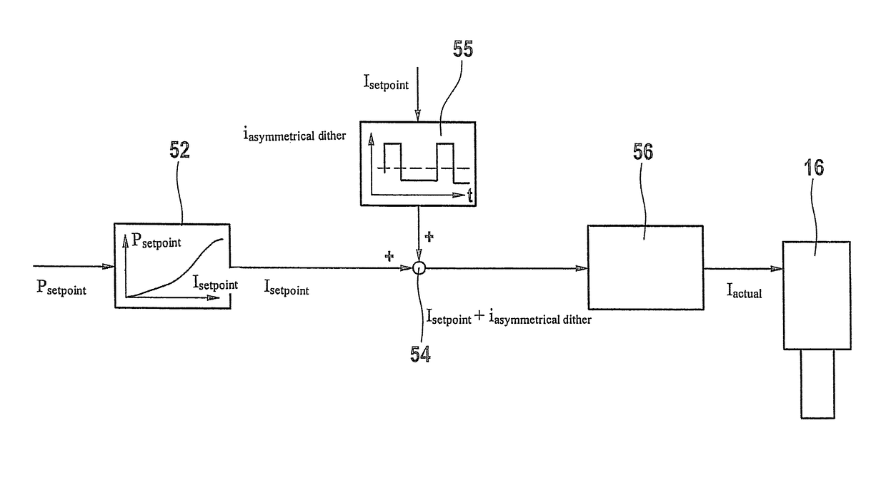
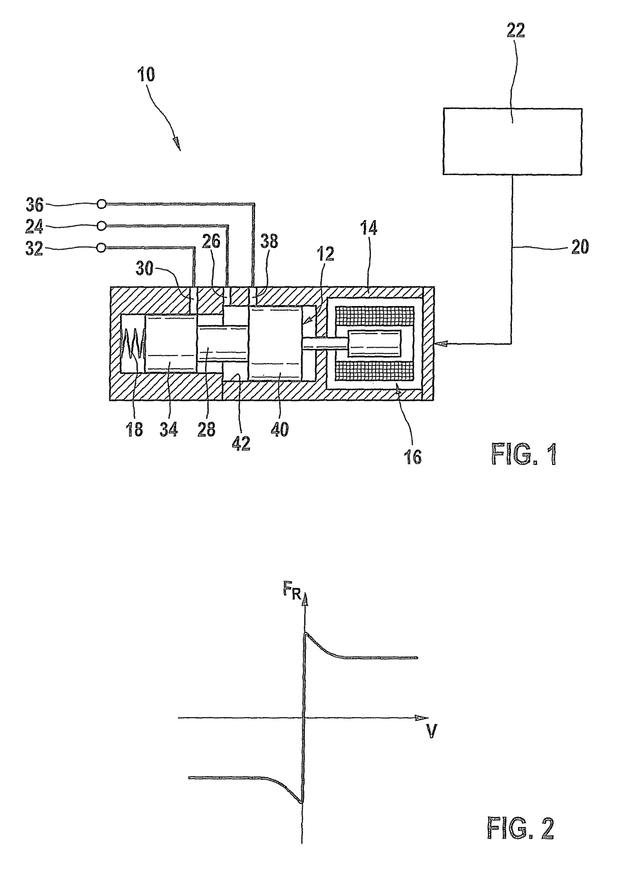
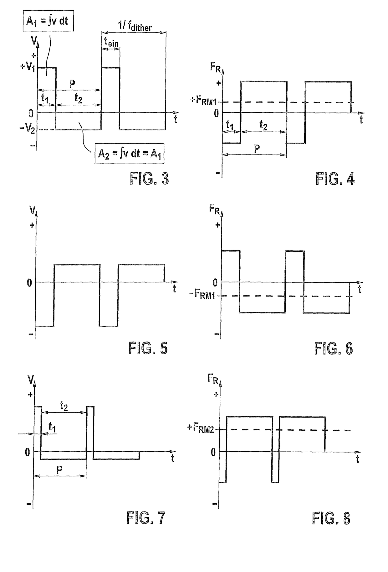
[0030]In FIG. 1, reference numeral 10 denotes a mechanical system as a whole that is developed as a proportioning valve. It includes a movable component in the form of a stepped valve slide 12, which is guided in a housing 14 in a sliding fit and is thus movable relative to housing 14 under friction. Proportioning valve 10 also includes an electromagnetic operating device 16, which acts upon valve slide 12 in the one direction, and a valve spring 18, which acts upon valve slide 12 in the other direction. Electromagnetic operating device 16 is controlled by a control signal 20, which is provided by an output stage (not shown) of a control and regulating device 22.

[0031]Proportioning valve 10, in this instance, is a pressure-regulating valve. Here, it regulates the pressure at a regulating connection 24, which is connected to a housing duct 26 that is located approximately at the level of a middle section 28 of valve slide 12, that has a comparatively small diameter. A second housing ...


PUM


Abstract

A mechanical system has a component, which is movable under friction. An oscillating micromotion (dither) is impressed upon the component, which, if necessary, is added to a non-oscillating base motion of the component. It is provided that the micromotion (without the base motion that is additional, if necessary) is faster within a period of the oscillation in the one direction and is of shorter duration than in the opposite direction (asymmetrical dither).

Description

RELATED APPLICATION INFORMATION[0001]The present application claims priority to and the benefit of German patent application no. 10 2009 002 852.8, which was filed in Germany on May 6, 2009, the disclosure of which is incorporated herein by reference.FIELD OF THE INVENTION[0002]The present invention relates to a method for operating a mechanical system. The subject matter of the present invention also relates to a computer program, an electrical storage medium as well as a control and / or regulating device.BACKGROUND INFORMATION[0003]It is understood that, in mechanical systems, in the case of two components which are movable relative to each other under friction, a frictional force directed counter to the direction of motion occurs when the components are moved relative to each other. In many mechanical systems, this frictional force may act interferingly, since it may prevent a clear stationary state from setting in. In addition, it leads to hysteresis in response to reversing moti...

Claims


Application Information

Patent Timeline
Patent Type & Authority Patents(United States)
IPC IPC(8): F16H21/44G05D17/00F15B13/044G05D19/02F15B13/04
CPCF15B13/044F15B13/0402G05D19/02F15B2211/7733Y10T74/18888
Inventor ZIPPERER, MARTINMOSER, WINFRIEDSCHNELLE, KLAUS-PETERSCHUMACHER, STEFFENKRAUTER, LOTHARDEPONTE, RENEOTT, CHRISTOF
Owner ROBERT BOSCH GMBH
Why Eureka
Try Eureka