
HVAC system control integrated with demand response, on-site energy storage system and on-site energy generation system

a technology of demand response and hvac system, applied in the direction of electrical energy, instruments, heating types, etc., can solve the problems of not deciding how the load of hvac system resulting from the optimized control is optimal, and commercial and residential buildings consume a large amount of energy

Inactive Publication Date: 2017-05-16
INT BUSINESS MASCH CORP
View PDF20 Cites 14 Cited by
  • Summary
  • Abstract
  • Description
  • Claims
  • Application Information

AI Technical Summary

Benefits of technology

This approach minimizes total energy costs and greenhouse gas emissions while ensuring thermal comfort, stabilizing energy supply, and promoting smart grid usage by optimally sourcing energy loads through a combination of grid, stored, and generated electricity.

Problems solved by technology

Buildings such as commercial and residential buildings consume a large amount of energy, and approximately half of the energy consumption is taken up by Heating Ventilation and Air Conditioning (HVAC) systems in the buildings.
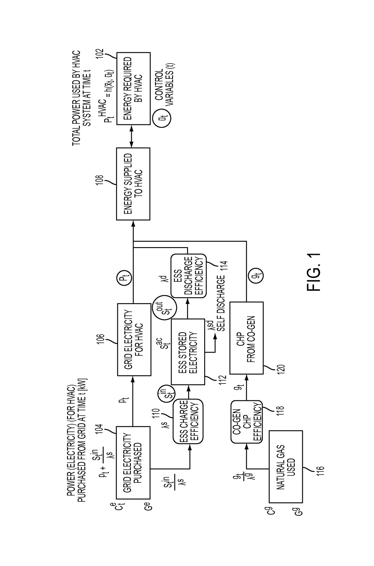
However, that approach does not decide how the load of HVAC system resulting from the optimized control is optimally sourced through energy supplies, e.g., grid electricity with demand response, on-site stored electricity (e.g., lead acid battery) and on-site generated electricity (e.g., combined heat and power (CHP) generator).

Method used


Image

  • HVAC system control integrated with demand response, on-site energy storage system and on-site energy generation system
  • HVAC system control integrated with demand response, on-site energy storage system and on-site energy generation system
  • HVAC system control integrated with demand response, on-site energy storage system and on-site energy generation system

Examples


Embodiment Construction

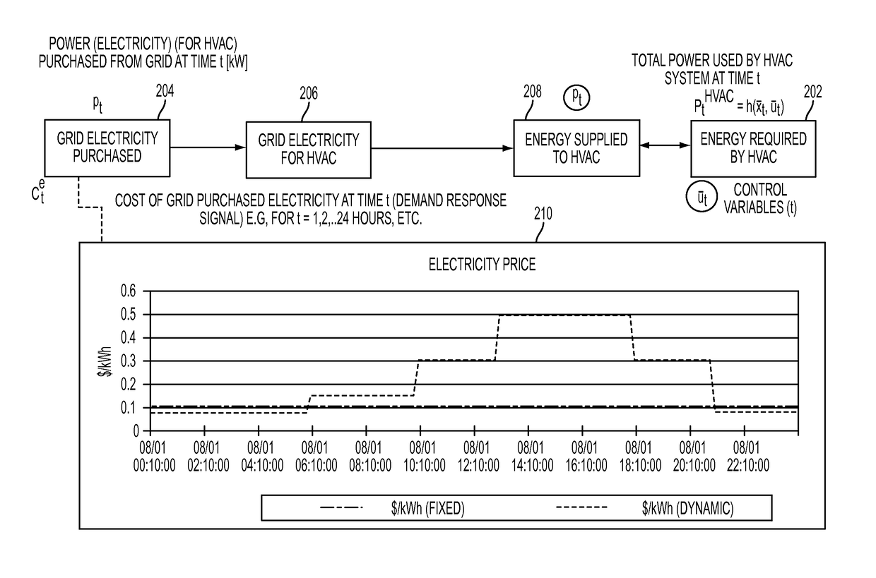
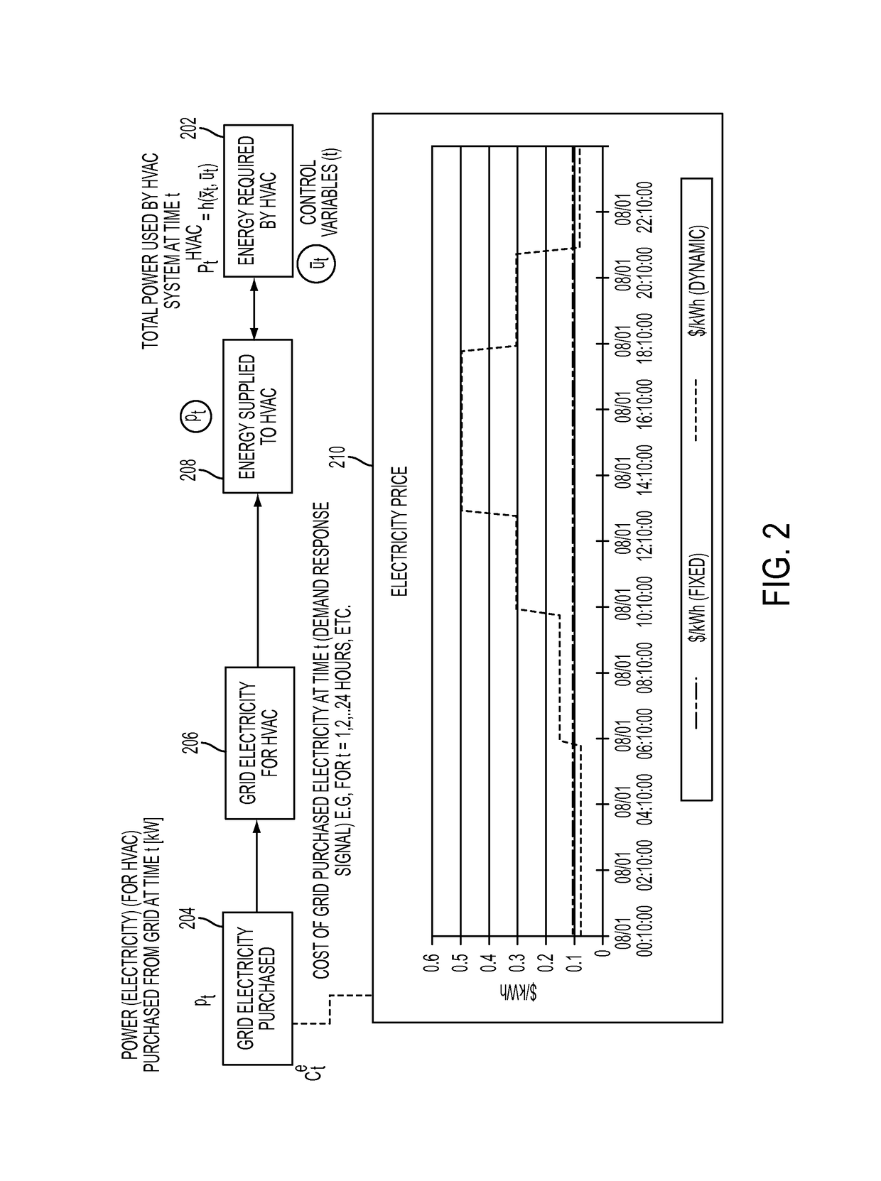
[0017]A method and computer system may be presented that in one embodiment compute control profiles of an HVAC system as well as how the power (load) needed by the HVAC system is optimally sourced through optimized combination of grid purchased energy with demand response, on-site stored energy and on-site generated energy. In one aspect, the control profiles are optimal. The control profile is then communicated to the controller (e.g., a Building Automation System) to control the HVAC system. In one embodiment, the method includes a Model Predictive Control (MPC) framework for a building HVAC control that reduces energy costs of HVAC operations proactively using an optimal control method and considering the dynamic price of grid purchased electricity, on-site stored electricity, and / or on-site generated electricity. The method and / or computer system can serve as an energy reduction and demand response tool that not only optimize the energy costs in buildings but also reduce energy ...


PUM


Abstract

A thermal behavior model of a building may be constructed based on time series data. Based on the constructed thermal behavior model, forecasted zone temperature and energy usage for a next control time period may be predicted. An objective function may be constructed based on at least a dynamically priced grid energy cost, occupant comfort matrix, and one or more of: energy storage system cost and associated operational cost, and energy generation system cost and associated green house emission cost and associated operational cost. Constraints may be constructed based on at least the forecasted zone temperature values and energy usage values for the next control time period. A control profile of the HVAC system and sourcing decision of energy load of the HVAC system may be determined simultaneously based on the objective function and the plurality of constraints.

Description

FIELD[0001]The present application relates generally to buildings and energy consumption, and more particularly to control systems and controlling Heating Ventilation and Air Conditioning (HVAC) systems.BACKGROUND[0002]Buildings such as commercial and residential buildings consume a large amount of energy, and approximately half of the energy consumption is taken up by Heating Ventilation and Air Conditioning (HVAC) systems in the buildings. A traditional approach to optimized HVAC control in a building is to compute an optimal control profile (e.g., a set point profile of each heating and / or cooling zone, supply flow rate or supply temperature of air handling unit (AHU)) that minimizes the total energy consumption while satisfying thermal comfort (e.g., zone temperature and humidity) and physical limitations of HVAC equipment (e.g., supply temperature, supply flow rate of AHU). Such traditional approaches typically assume that the electricity price is constant throughput the day.[0...

Claims


Application Information

Patent Timeline
Patent Type & Authority Patents(United States)
IPC IPC(8): G05B17/02G05B13/02G05B15/02G05D23/19F24F11/00G06Q50/06G05B13/04H02J3/00
CPCG05B17/02F24F11/0012F24F11/0034G05B13/02G05B13/04G05B15/02G05D23/1904G05D23/1917G05D23/1923G06Q50/06F24F2011/0047F24F2011/0058H02J2003/003H02J2003/007Y02P80/11F24F11/30F24F2110/10F24F2120/10F24F2140/60F24F2130/00F24F2130/10Y04S50/16F24F11/80F24F11/58F24F11/47F24F11/63F24F11/74F24F11/52H02J3/003H02J2203/20Y02P80/10
Inventor HORESH, RAYALEE, YOUNG M.LIBERTI, LEO S.
Owner INT BUSINESS MASCH CORP
Learn More