Frequency-variable hand rubbed-type motor speed reduction clutch apparatus, and washing machine

a technology of speed reduction clutch and frequency variable, which is applied in the field of washing machines, can solve the problems of low efficiency of washing machine speed reduction clutch, large noise, and poor practicability, and achieve the effect of reducing the height of the motor speed reduction clutch, small volume, and compact installation structur

Inactive Publication Date: 2017-05-23
HAIER GRP CORP +1
View PDF15 Cites 0 Cited by
  • Summary
  • Abstract
  • Description
  • Claims
  • Application Information

AI Technical Summary

Benefits of technology

[0023]Further, the dehydration shaft sleeve is formed by two segments of shaft sleeves that are coaxial and have different diameters, and whose internal periphery is provided with splines fitted to the input shaft. The upper-segment shaft sleeve is relatively small in outer diameter, and passes through an inner hole of the clutch shaft sleeve and then contacts an end portion of the dehydration shaft. The lower-segment shaft sleeve is relatively large in outer diameter, and an upper end of the lower-segment shaft sleeve is provided with spline teeth fitted to the clutch shaft sleeve, so as to be engaged with or disengaged from the clutch shaft sleeve. The external periphery of the dehydration shaft sleeve is wrapped with a circle of shock absorption pad. The shock absorption pad made of a rubber material is disposed between the clutch shaft sleeve and the motor, so as to reduce an effect of vibration of the motor on the dehydration shaft sleeve.
[0027]By means of the foregoing technical solution, advantages of the present invention over the prior art lie in that: the clutch shaft sleeve is engaged with or disengaged from the dehydration shaft sleeve by means of splines, so as to achieve an objective of switching between dehydration and washing modes of the washing machine. More particularly, the control apparatus formed by the connection arm, the braking arm, the shifting fork and the clutch spring transfer a controllable traction acting force of the traction motor to the clutch shaft sleeve or the braking belt, so as to implement a fitted action between the clutch shaft sleeve and the braking belt, and achieve an objective that under the action of the clutch shaft sleeve and the braking belt, the dehydration shaft rotates jointly together with the rotor or freely rotates or grasps and does not move. Because in the present invention, the clutch shaft sleeve and the clutch spring are installed in space inside the motor, and compared with the conventional clutch formed by components such as a ratchet wheel, a clutch spring, and a shaft sleeve, the present invention is smaller in volume, and more in compact in installation structure, the height of the motor speed reduction clutch is effectively reduced, and the whole washing capacity of the washing machine may be effectively increased. The present invention is simple in structure and notable in effect, and is suitably popularized and used.

Problems solved by technology

The type of washing machine speed reduction clutches are low in efficiency, large in noise, and relatively poor in practicability; therefore, related technicians propose a technical solution in which a motor and a clutch are perpendicularly and concentrically installed.
However, in the technical solution of the patent, a single-phase asynchronous motor originally installed beside a washing machine speed reduction clutch is only simply directly perpendicularly installed below the clutch; because efficiency of the motor is not considerably improved, the washing manner is single, functions are simple, installation and connection thereof are complex, and the precision requirement is high, mass production is not suitable, and the washing machine cannot implement frequency-variable rubbing and kneading washing, or frequency-variable multi-speed dehydration.
However, the motor of the structure is complex in connection, and can only implement an ordinary washing manner, connection parts of main components are relatively large in quantity, requirements on clutch installation precision are excessively high, and a disadvantage of a high fault rate exists in the motor, and therefore the technical solution of the patent is not suitable for mass production.

Method used


Image

  • Frequency-variable hand rubbed-type motor speed reduction clutch apparatus, and washing machine
  • Frequency-variable hand rubbed-type motor speed reduction clutch apparatus, and washing machine
  • Frequency-variable hand rubbed-type motor speed reduction clutch apparatus, and washing machine

Examples


embodiment 1

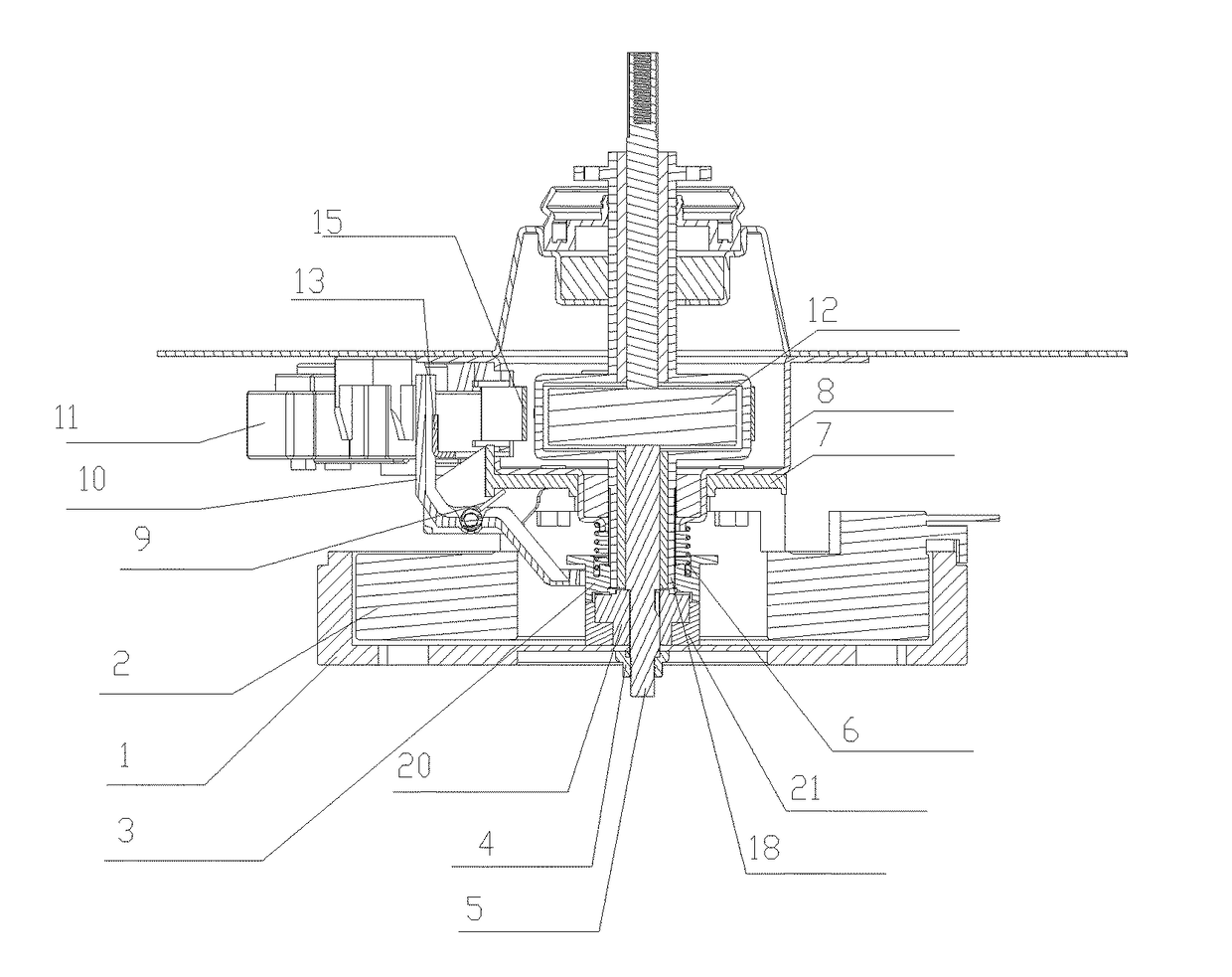
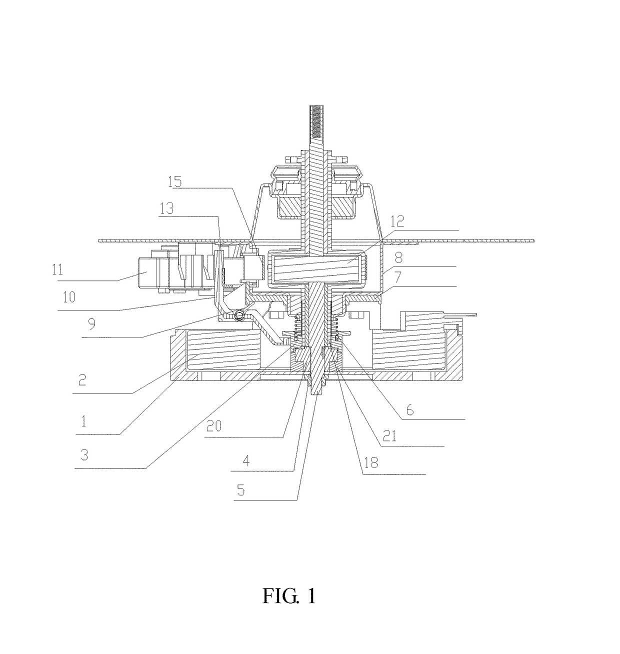
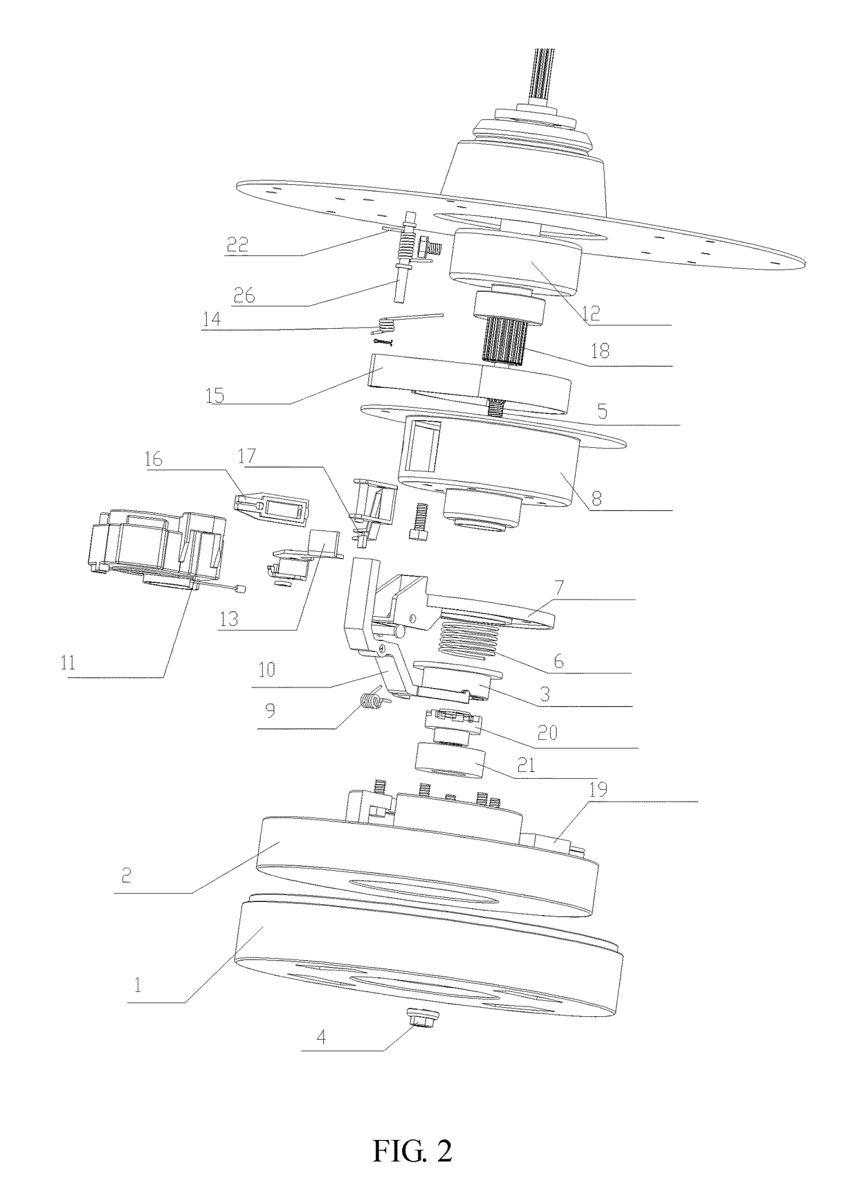
[0034]As shown in FIG. 1 and FIG. 2, in this embodiment, a frequency-variable hand rubbed-type motor speed reduction clutch apparatus is introduced and includes: an input shaft 5, and a motor rotor 1 fixedly connected to the input shaft 5, where a dehydration shaft sleeve 20 rotates together with the input shaft 5 is installed on the input shaft 5, and the dehydration shaft sleeve 20 is engaged with or disengaged from the input shaft 5 by means of a clutch shaft sleeve 3 sliding up and down; a braking wheel 12 is connected to a dehydration shaft 18; under the action of a control apparatus, a traction motor 11 generates a displacement to tract a braking belt 15 to change from grasping the braking wheel 12 to loosening the braking wheel 12; and the traction motor 11 generates a displacement again so that the clutch shaft sleeve 3 changes from being disengaged from to engaged with the input shaft 5.

[0035]In this embodiment, the motor is formed by a rotor 1 connected to the input shaft ...

embodiment 2

[0043]As shown in FIG. 1 and FIG. 2, in this embodiment, a specific connection structure of the control apparatus of the clutch apparatus is as follows: one end of the connection arm 16 is provided with an installation slot fixedly connected to a displacement output end of the traction motor 11, and another end of the connection arm 16 is formed by a square through-hole; and the braking arm 17 is installed in the square through-hole. The braking arm 17 is installed at a lower portion of an installation pin 26 and rotates around the installation pin 26, and the installation pin 26 is disposed on the housing 8; and one end of the braking arm 17 is connected to the connection arm 16, another end of the braking arm 17 is used as the first output end fixedly connected to the braking belt 15, and the second output end in contact with or disengaged from the compression bar 13 is further disposed on the braking arm 17. The compression bar 13 is installed at an upper portion of the installat...

embodiment 3

[0052]This embodiment introduces a method for controlling a frequency-variable hand rubbed-type motor speed reduction clutch apparatus, where the method includes: driving, by a traction motor, a connection arm to generate a first displacement, so that a braking belt is disengaged from a braking wheel on a dehydration shaft, and the dehydration shaft can freely rotate; and driving the connection arm to generate a second displacement, so that a clutch shaft sleeve is engaged with a dehydration shaft sleeve, and the dehydration shaft rotates together with an input shaft.

[0053]The frequency-variable hand rubbed-type motor speed reduction clutch apparatus includes three states: a first state, where the braking belt grasps the braking wheel, and the dehydration shaft sleeve is disengaged from the clutch shaft sleeve; in this case, the input shaft may rotate together with a rotor of the motor, and the dehydration shaft is locked tightly and cannot rotate;

[0054]a second state, where the bra...


PUM


Abstract

A frequency-variable hand rubbed-type motor speed reduction clutch apparatus, and a washing machine. The clutch apparatus includes: an input shaft (5) connected to a motor rotor (1); a dehydration shaft (18); and a clutch apparatus housing (8) in which the input shaft (5) and the dehydration shaft (18) are mounted. A braking wheel (12) and a braking belt (15) fitted to the braking wheel (12) are disposed on the dehydration shaft (18). A dehydration shaft sleeve (20) rotating together with the input shaft (5) is mounted on the input shaft (5). A clutch shaft sleeve (3) sliding up and down, and engaging with or separated from the dehydration shaft sleeve (20) is mounted on the dehydration shaft (18). The braking belt (15) and the clutch shaft sleeve (3) are separately connected to a traction motor (11) by means of a control apparatus.

Description

CROSS-REFERENCE TO RELATED APPLICATIONS[0001]This application is a continuation application of International Patent Application No. PCT / CN2013 / 090073, filed Dec. 20, 2013, which itself claims the priority to Chinese Patent Application No. 201310356422.8 filed Aug. 15, 2013 in the State Intellectual Property Office of P.R. China, which are hereby incorporated herein in their entireties by reference.FIELD OF THE INVENTION[0002]The present invention relates generally to the field of washing machines, and more particularly to a frequency-variable hand rubbed-type motor speed reduction clutch apparatus and a washing machine.BACKGROUND OF THE INVENTION[0003]In the prior art, such as the vast majority of washing machines newly released in the market, a washing machine speed reduction clutch and a single-phase asynchronous motor are abreast installed, and transmission is performed by using a belt wheel and a belt. The type of washing machine speed reduction clutches are low in efficiency, l...

Claims


Application Information

Patent Timeline
Patent Type & Authority Patents(United States)
IPC IPC(8): F16D67/06D06F37/20D06F37/30H02K7/10
CPCF16D67/06D06F37/206D06F37/30H02K7/10D06F17/08F16D67/02
Inventor LV, PEISHIYANG, LINZHANG, GANGJINTIAN, YUNHAO, XIAOFENG
Owner HAIER GRP CORP
Why Eureka
Try Eureka