
Embedded coins for HDI or SEQ laminations

Active Publication Date: 2017-05-23
FLEX LTD
View PDF60 Cites 12 Cited by
  • Summary
  • Abstract
  • Description
  • Claims
  • Application Information

AI Technical Summary

Benefits of technology

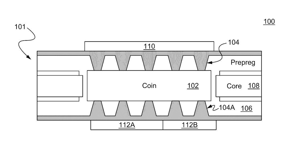
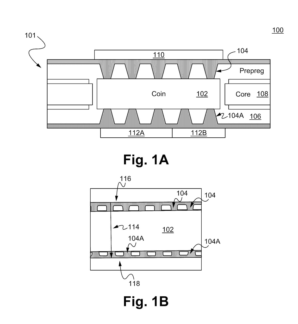
The patent text describes a method and device for improving heat transfer in High Density Interconnect (HDI) boards. This is achieved by embedding a high heat transfer efficiency material, such as a metal coin, in sub-layers and drilling micro-vias in outer layers. The micro-vias are landed on the metal coin and can transfer heat efficiently from the top side of the PCB to the bottom side of the PCB via the embedded coin. The technical effect is improved heat transfer in HDI boards.

Problems solved by technology

The trend of having high circuit density leads to problems of thermal dissipation in the PCB (printed circuit board) assembly process.

Method used


Image

  • Embedded coins for HDI or SEQ laminations
  • Embedded coins for HDI or SEQ laminations
  • Embedded coins for HDI or SEQ laminations

Examples


Embodiment Construction

[0014]Reference is made in detail to the embodiments of the present invention, examples of which are illustrated in the accompanying drawings. While the invention is described in conjunction with the embodiments below, it is understood that they are not intended to limit the invention to these embodiments and examples. On the contrary, the invention is intended to cover alternatives, modifications and equivalents, which can be included within the spirit and scope of the invention as defined by the appended claims. Furthermore, in the following detailed description of the present invention, numerous specific details are set forth in order to more fully illustrate the present invention. However, it is apparent to one of ordinary skill in the prior art having the benefit of this disclosure that the present invention can be practiced without these specific details. In other instances, well-known methods and procedures, components and processes have not been described in detail so as not...


PUM


Abstract

A method of and a device for dissipating / transferring heat through one or more solid vias and embedded coins are disclosed. The method and device disclosed herein can be used to transfer heat for a High Density Interconnect (HDI) board.

Description

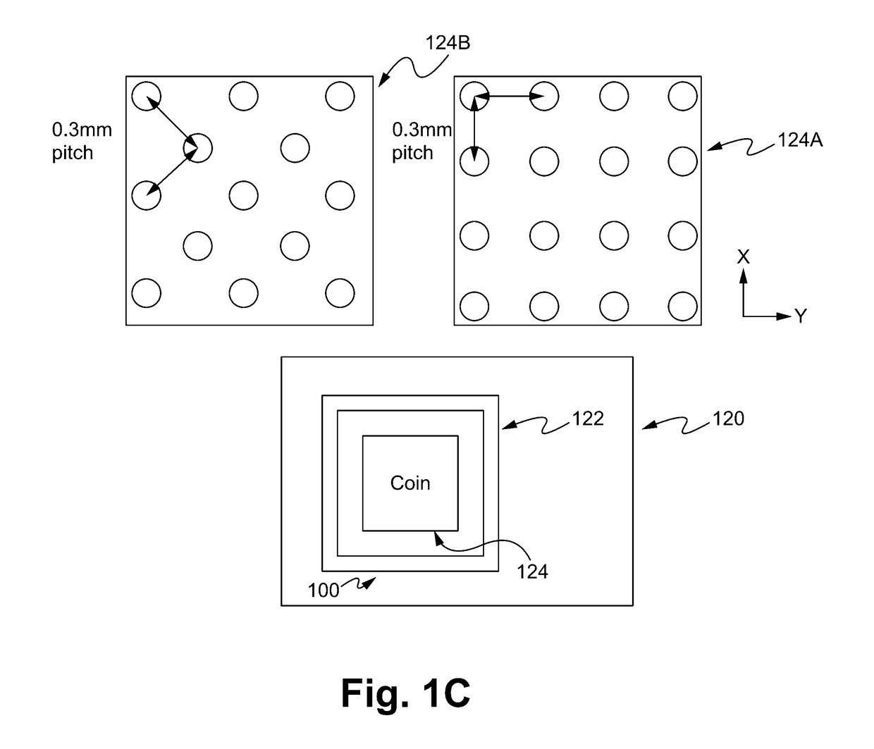
FIELD OF THE INVENTION[0001]The present invention relates to the field of electronic manufacturing. More specifically, the present invention relates to heat dissipation of electronic devices.BACKGROUND OF THE INVENTION[0002]The trend of having high circuit density leads to problems of thermal dissipation in the PCB (printed circuit board) assembly process. Improved efficiency of thermal dissipation is helpful to make the devices work properly, especially for high power system and its IC packaging.[0003]In some cases, a metal coin is embedded inside the PCB under the high power component or the IC chip, such that heat can be dissipated to the other side of the PCB and can be carried away by another heat sink device or a cabinet physically contacted to the coin.SUMMARY OF THE INVENTION[0004]A method of and a device for dissipating / transferring heat through one or more solid vias and embedded coins are disclosed. The method and device disclosed herein can be used to improve heat transf...

Claims


Application Information

Patent Timeline
IPC IPC(8): H05K1/00H05K3/44H05K1/02
CPCH05K1/0206H05K1/0207H05K3/445H05K1/0204H05K3/4602H05K2201/10416H01L2224/2518H01L2224/04105
Inventor JACOBSSON, HENRIKYU, PUI YIN
Owner FLEX LTD
Learn More