Vacuum-cleaning robot

a vacuum robot and vacuum technology, applied in the field of self-propelled vacuum cleaners, can solve the problems of large reduction of the accuracy of navigation, insufficient suction characteristics and suction-opening design of vacuum robots, and the current vacuum robot models are still far behind the technically possible suction performan

Active Publication Date: 2017-05-30
WESSEL WERK
View PDF3 Cites 10 Cited by
  • Summary
  • Abstract
  • Description
  • Claims
  • Application Information

AI Technical Summary

Benefits of technology

[0010]Thus the vacuum-cleaning tool is a preassembled module and is not an integral part of the main housing of the vacuum robot, but rather is a preassembled module attached to it. Thus, it is possible with a vacuum robot model that has already been optimized with regard to navigation, drive, and suction power performance, to increase suction performance by using an optimized preassembled module and a cleaning tool by a specialized manufacturer. The individual elements of the vacuum-cleaning tool are coordinated to achieve the best possible suction result. For different requirement profiles—for example with different dirt types—certain specific elements can be combined with each other. For the suction characteristics in general the design of the front suction-opening edge is decisive. Because of the rigid design of the front suction-opening edge especially good suction power is achieved. In this connection “rigid” means that the shape of the suction-opening edge does not change when used as intended beyond the range of manufacturing tolerances. So that obstacles can be gotten over, forward in the travel direction of the bottom opening on the roller chamber there is an angled slide of at least 10 mm. The reference point for this height is a smooth floor where the vacuum cleaner rests. Preferably the height of the angled slide should be about 15 mm. With an angled slide a steady profile is meant with a pitch angle of preferably not more than 45°. Finally with the combination of a rotationally driven cleaning roller and the aspiration of airflow from inside the roller chamber further improvement in the cleaning action can be achieved, without generating additional friction on the ground through excessively strong suction airflow that could impair navigation of the vacuum robot.
[0012]In a preferred embodiment the vacuum-cleaning tool is arranged vertically movably or pivotally mounted on the main housing and has rollers for bottom side support. In this manner the suction-cleaning tool is separate from the weight of the other element of the robot, namely the main housing with drive, blower, power supply, and air guide and dirt separator. The pivotal or spring mounting of the suction cleaning tool on the main housing ensures that the suction cleaning tool be deflected upward when the vacuum robot is used with a high-pile floor covering and the robot main housing as a result of its weight sinks somewhat deeply into the pile. The vertical movability or pivotability allows the suction-cleaning tool to always conform to varying floor irregularities. The suction cleaning tool can be supported on the main housing via springs. In addition the suction-cleaning tool can be provided with rollers or floor slides to ensure that the leading suction-opening mouth during vacuuming of a smooth floor maintains a defined spacing of preferably 1 to 2 mm from the floor surface.

Problems solved by technology

Slip of the drive wheels—especially if this occurs unevenly—can massively reduce the accuracy of the navigation.
Previously however the suction characteristics and the suction-opening design of a vacuum robot were not adequately addressed.
As a result the current vacuum robot models are still far behind the technically possible suction performance.

Method used


Image

  • Vacuum-cleaning robot
  • Vacuum-cleaning robot
  • Vacuum-cleaning robot

Examples


Embodiment Construction

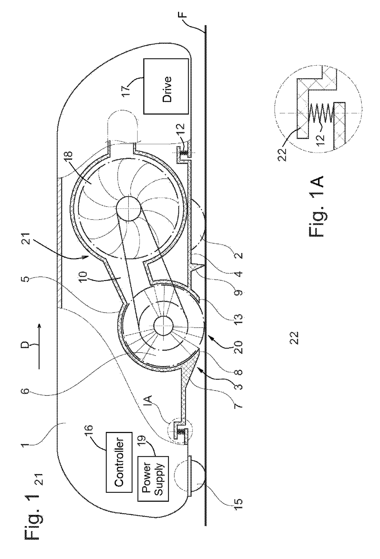
[0021]As seen in FIG. 1 a vacuum-cleaning robot according to the invention has a main housing 1, typically of injection-molded plastic holding a schematically illustrated controller 16 and drive 17, as well as a battery serving as power supply 19, antennas, and such.

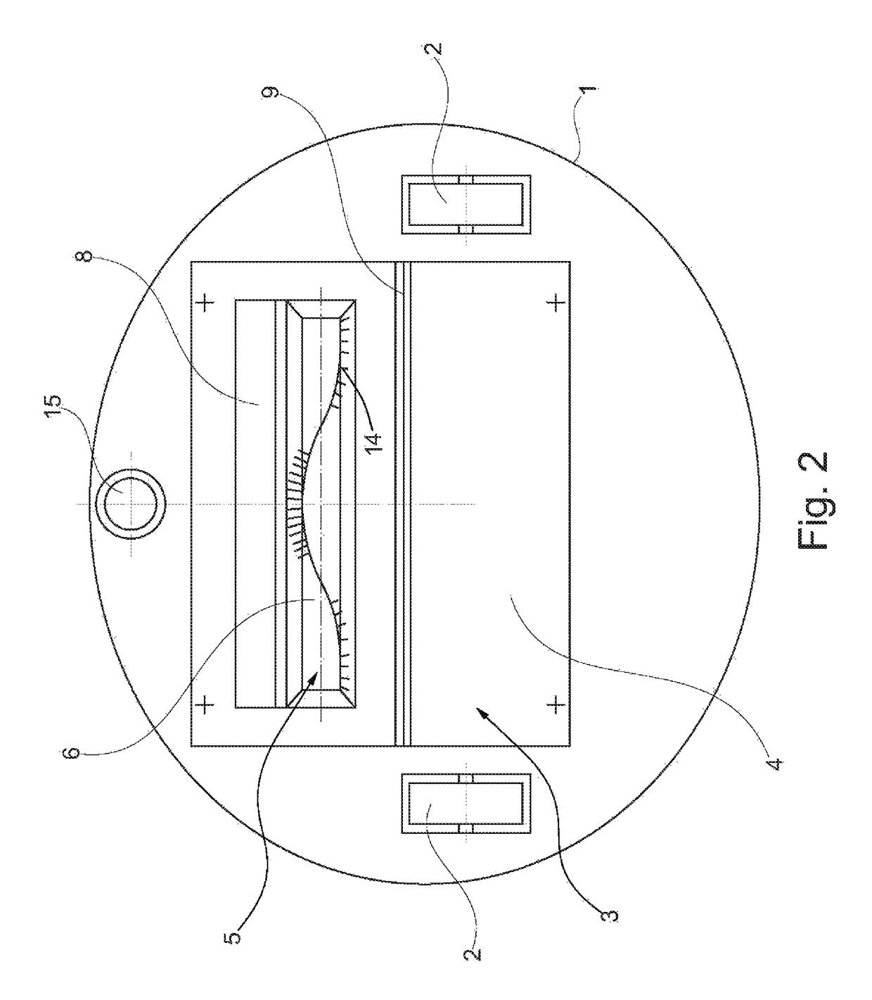
[0022]The generally planar rigid bottom wall of the main housing 1 carries two coaxial drive wheels 2 that are rotated by the drive 17 and that can be differentially rotated to steer the device. A ball-type caster 16 at the front end of the main housing bottom wall provides the third point of support, making the main housing 1 stable even on an uneven floor surface F.

[0023]The main housing also holds a blower 18, structure including a duct 10 connected to the suction side of the blower 18 for drawing in air and separating dirt. The design of such a vacuum cleaner, which is also called a vacuum robot, has been known for a long time. The weight of the basic body of the vacuum robot is borne by the two driven wheels 2 and t...


PUM


Abstract

A self-propelled vacuum cleaner has a main housing having a bottom wall formed with an aperture, floor-engaging wheels on the main housing, and a drive in the main housing for rotating the wheels and advancing the main housing in a normal horizontal travel direction. A module housing projecting through the aperture forms a brush compartment defining a downward directed suction opening having relative to the direction a leading edge and a trailing edge. The module housing is supported in the main housing for limited vertical movement of the module housing relative to the main housing. A brush in the module housing is engageable through the opening with a floor beneath the opening, and a blower in the module housing having an intake connected via a duct to the brush compartment for aspirating air through the opening and past the brush into the module housing.

Description

FIELD OF THE INVENTION[0001]The present invention relates to self-propelled vacuum cleaner. More particularly this invention concerns vacuum-cleaning robot.BACKGROUND OF THE INVENTION[0002]A typical vacuum robot comprises a main housing and a drive with at least two power-driven wheels. A vacuum blower, a duct connected to the vacuum side of the blower to guide air and separate out dirt and a power source to supply power are provided in the main housing.[0003]The drive of the vacuum robot has a preferred travel direction in which the vacuum cleaner is moved by the high velocity power wheels. Cornering is effected using different rotation speeds of the drive wheels. Turning in place with counter-rotating wheels is also possible.[0004]So that the vacuum robot can move autonomously in the room to be cleaned, it has a navigation system, typically operating under GPS or odometric protocols. Often the distance traveled is inferred from the movement data from the drive. Slip of the drive w...

Claims


Application Information

Patent Timeline
Patent Type & Authority Patents(United States)
IPC IPC(8): A47L9/02A47L9/28A47L9/00A47L9/08A47L9/04A47L11/40A47L9/06
CPCA47L9/2852A47L9/009A47L9/0494A47L9/06A47L9/08A47L11/4058A47L9/066A47L9/0666A47L2201/00
Inventor RIEHL, KLAUS-DIETER
Owner WESSEL WERK
Why Eureka
Try Eureka