X-ray imaging system and image processing device

a technology of image processing and imaging system, applied in the field of x-ray imaging system and image processing device, to achieve the effect of low cost and image degradation

Active Publication Date: 2017-05-30
KONICA MINOLTA INC
View PDF19 Cites 4 Cited by
  • Summary
  • Abstract
  • Description
  • Claims
  • Application Information

AI Technical Summary

Benefits of technology

[0007]Objects of the present invention include preventing, at low cost, image degradation due to error in a relative position of a grating moved in fringe scanning without adding a special sensor to detect the relative position of the grating to an X-ray imaging device.

Problems solved by technology

When each imaging is performed with error in the position of the grating, measured physical quantities have error and also a reconstructed image (s) generated on the basis of the taken moire fringe images has unevenness therein, which is undesirable.
However, in the technique described in International Patent Application Publication No. 2012 / 057022, a special sensor which can measure the position of a grating at 0.01 μm order needs to be added to an X-ray imaging device, which is costly.

Method used


Image

  • X-ray imaging system and image processing device
  • X-ray imaging system and image processing device
  • X-ray imaging system and image processing device

Examples


Embodiment Construction

[Configuration of X-Ray Imaging System]

[0021]Hereinafter, an embodiment of the present invention is described with reference to the drawings.

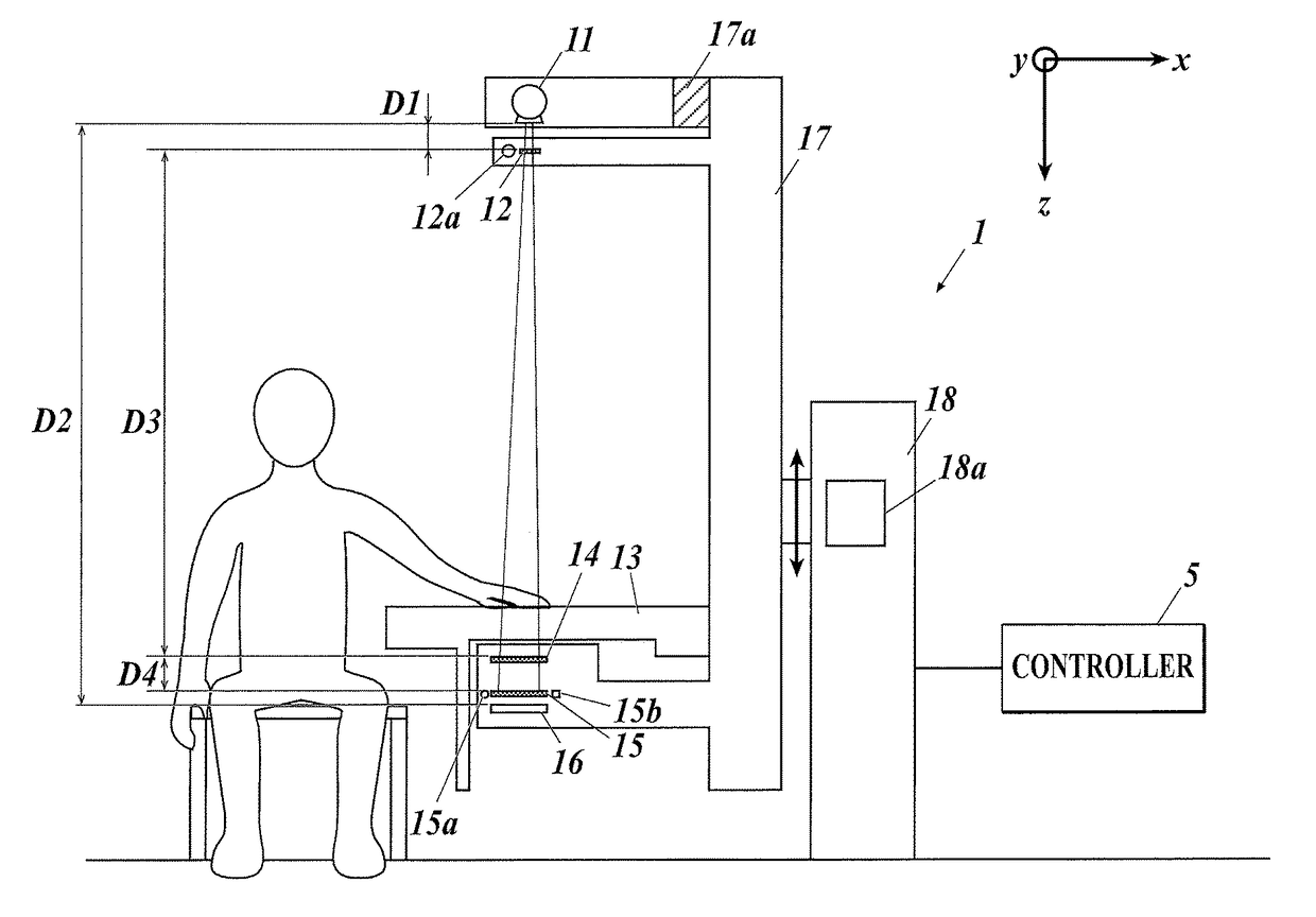
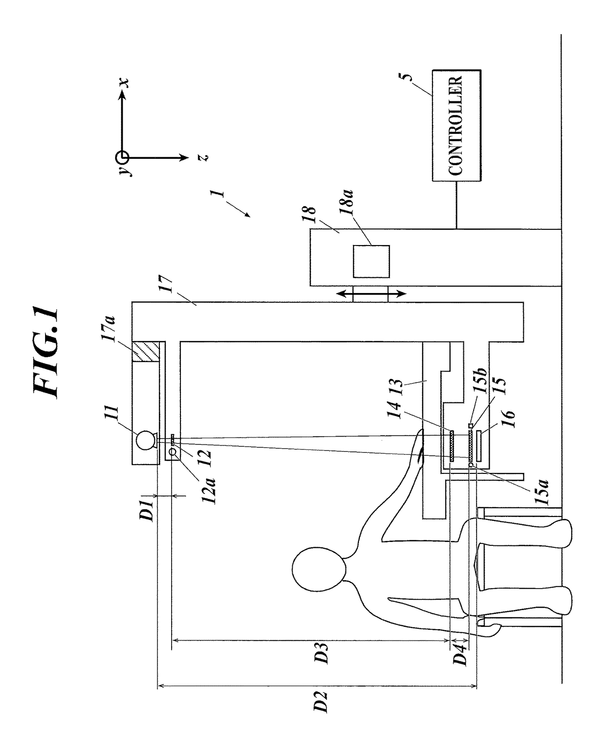
[0022]FIG. 1 shows an example of the configuration of an X-ray imaging system as an embodiment. The X-ray imaging system includes an X-ray imaging device 1 and a controller 5. The X-ray imaging device 1 performs X-ray imaging (fringe scanning) with a Talbot-Lau interferometer, and the controller 5 generates reconstructed images of a subject using a plurality of moire fringe images obtained by the X-ray imaging.

[0023]The X-ray imaging device 1 includes, as shown in FIG. 1, an X-ray source 11, a multi-slit (source grating) 12, a subject table 13, a first grating 14, a second grating 15, an X-ray detector 16, a support unit 17 and a main body unit 18.

[0024]The X-ray imaging device 1 is a vertical type, and the X-ray source 11, the multi-slit 12, the subject table 13, the first grating 14, the second grating 15 and the X-ray detector 16 are arrange...


PUM

PropertyMeasurementUnit
distance D1aaaaaaaaaa
heightaaaaaaaaaa

Abstract

An X-ray imaging system includes an X-ray imaging device and an image processing device including a reconstruction unit and an estimation unit. The X-ray imaging device uses a Talbot or Talbot-Lau interferometer including gratings disposed in a line. The X-ray imaging device obtains sets of moire fringe images by fringe scanning multiple times between which arrangement of the gratings is changed. In the fringe scanning, one of the gratings is moved relatively to the remaining grating. The reconstruction unit generates, on the basis of the sets, a reconstructed image which is a differential phase image, an X-ray absorption image and / or a small-angle scattering image. The estimation unit estimates, on the basis of the reconstructed image, a relative position of the moved grating from a reference position of the grating at each imaging in the fringe scanning.

Description

CROSS-REFERENCE TO RELATED APPLICATIONS[0001]This application is based upon and claims the benefit of priority under 35 U.S.C. 119 of Japanese Patent Application No. 2014-160428 filed Aug. 6, 2014, the entire disclosure of which, including the specification, claims, drawings and abstract, is incorporated herein by reference in its entirety.FIELD OF THE INVENTION[0002]The present invention relates to an X-ray imaging system and an image processing device.DESCRIPTION OF THE RELATED ART[0003]In order to obtain a high-resolution image with an X-ray imaging device with a Talbot interferometer or Talbot-Lau interferometer, there is used a fringe scanning method of performing imaging M times (M is a positive integer of more than 2) while moving one of gratings 1 / M of a slit interval of the grating in a slit interval direction each time imaging is performed, and reconstruction is performed with the images (moire fringe images) obtained thereby. However, the slit interval of a grating is abo...

Claims


Application Information

Patent Timeline
Patent Type & Authority Patents(United States)
IPC IPC(8): G06K9/00G01N23/20A61B6/00G01N23/04G06T11/00
CPCG06T11/00A61B6/4291A61B6/484A61B6/5205G01N23/04G01N23/20075G06T2207/10116G21K2201/067G06T11/006G01N23/041
Inventor KIYOHARA, JUNKO
Owner KONICA MINOLTA INC
Why Eureka
Try Eureka