

Display uniformity compensation method, optical modulation apparatus, signal processor, and projection system
a compensation method and display technology, applied in the field of illumination and display, can solve the problems of reducing the dynamic range of the display, affecting the visual effect, and many applications, and achieve the effect of enhancing the uniformity of image brightness of the display unit and avoiding a reduction of the dynamic range of the displayed imag
- Summary
- Abstract
- Description
- Claims
- Application Information
AI Technical Summary
Benefits of technology
Problems solved by technology
Method used
Image

Examples
first embodiment
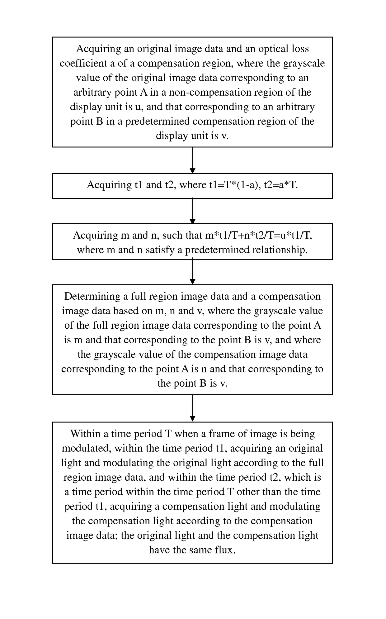
[0059]Refer to FIG. 1, which is a flowchart of a display uniformity compensation method according to an embodiment of the present invention. As shown in FIG. 1, this embodiment includes the following method steps:
[0060]S11: Acquiring an original image data and an optical loss coefficient a of a compensation region, where the grayscale value of the original image data corresponding to an arbitrary point A in a non-compensation region of the display unit is u, and that corresponding to an arbitrary point B in a predetermined compensation region of the display unit is v.
[0061]In a projection system of current technology, the optical modulation device typically includes a signal processor and an optical modulator unit, where the optical modulator unit includes multiple independently controllable pixel units, such as micro-vibration mirror units or liquid crystal units. The signal processor acquires image signal inputted from the user and converts it to image data, or directly acquires i...
second embodiment
[0115]In the first embodiment, the grayscale value q of the compensation image data for the point B is equal to the grayscale value v of the original image data for the point B, and the brightness uniformity of the compensation region and non-compensation region of the display unit is achieved by controlling the time periods t1 and t2 such that t2 / t1=a / (1−a). However, in practice, under the condition that the flux of the original light and compensation light are kept the same, the time periods can also be such that 02 / t1<a / (1−a), and a predetermined grayscale compensation value p is obtained; then, by adding to the grayscale value q at the point B in the compensation image data (the value in the first embodiment, q=v) the grayscale compensation value p, i.e. by letting q=v+p, to increase the image brightness of the compensation region, the brightness uniformity of the compensation region and non-compensation region may be achieved. Below are more detailed explanations.
[0116]Refer to...
third embodiment
[0129]In the second embodiment, when f is less than 1, and the flux of the original light and compensation light are kept the same, by adding a predetermined grayscale compensation value to the grayscale value of each pixel in the compensation region of the compensation image data, the brightness of the compensation region and non-compensation region of the display unit are made uniform.
[0130]In this embodiment, on the other hand, when f is less than 1, during the time period when the modulating device modulates the compensation image data, the predetermined grayscale compensation value for each pixel in the compensation region is set to 0; but by increasing the drive current for the compensation light source of the light source system, i.e. by making the flux of the compensation light received by the modulating device greater than the flux of the original light, the image brightness is increased in the compensation region of the display unit during the time period of modulating the...
PUM
 Abstract
Description
Claims
Application Information