
Extended residence time centrifugal contactor design modification and centrifugal contactor vane plate valving apparatus for extending mixing zone residence time

a centrifugal contactor and residence time technology, applied in the field of extracting moieties, can solve the problems of solution degradation, irradiation of solution, and only extracting elements with fast kinetics, and achieve the effects of reducing the effective entrance flow area, and ensuring the effect of stability

Active Publication Date: 2017-06-06
UCHICAGO ARGONNE LLC
View PDF3 Cites 3 Cited by
  • Summary
  • Abstract
  • Description
  • Claims
  • Application Information

AI Technical Summary

Benefits of technology

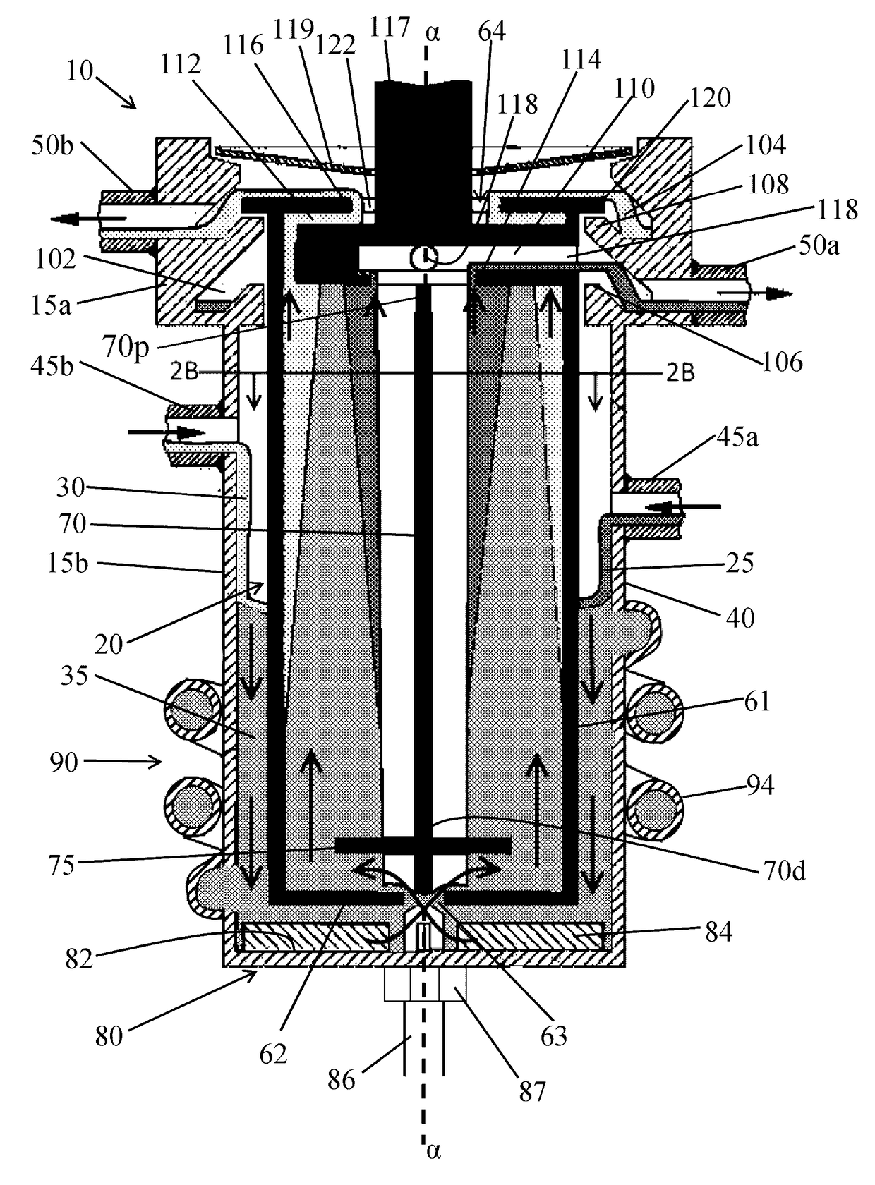
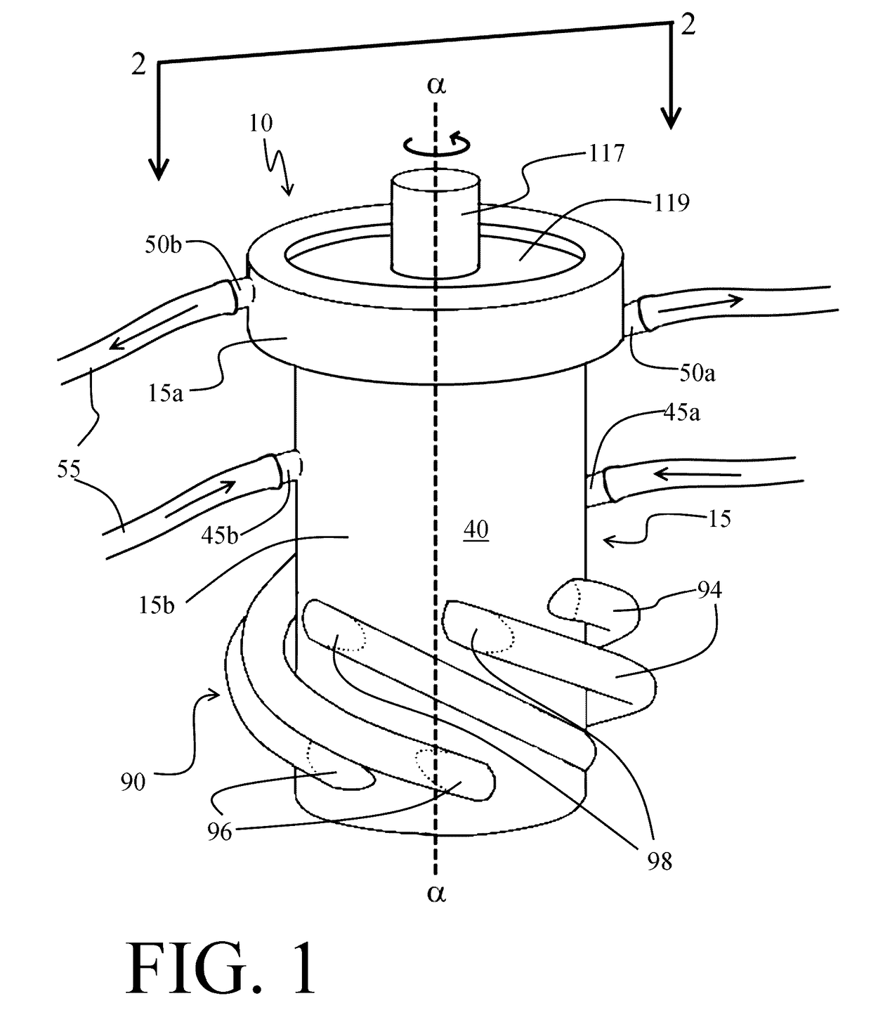
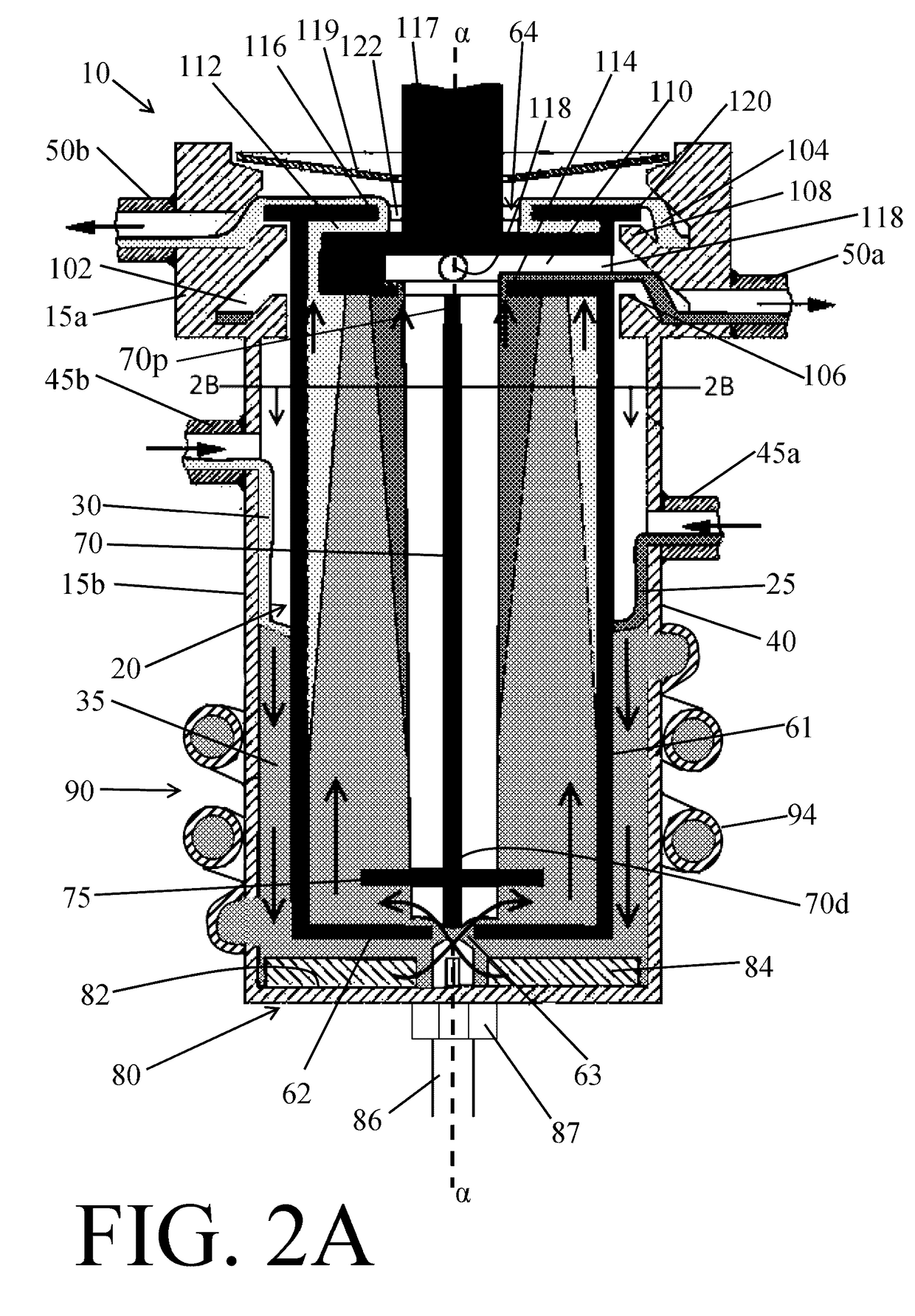
[0012]Another object of the present invention is to provide an annular centrifugal contactor with a mixing zone that can increase fluid residence times inside the contactor. A feature of the present invention is that the mixing zone contains multiple helical tubes that recirculate fluid from the bottom of the mixing zone to the top of the mixing zone. An advantage of the present invention is that residence time in the mixing zone can be at least doubled. A further advantage of the present invention is that it can be used for kinetically challenged extractions, such as actinide-lanthanide separations, while also still being suitable for reactions with faster kinetics
[0013]A further object of the present invention is to provide an annular centrifugal contactor in which the fluid throughput into the rotor can be restricted such that the mixing zone volume can be adjusted and maintain adequate holdup even at very low total throughput. A feature of the present invention is that the valve stem in the vane plate can be adjusted downwardly to increase or upwardly to decrease the effective entrance flow area of the rotor inlet and thus control the amount of fluid entering the rotor at a given time. Another feature of the present invention is that adjustment of the vane plate stem can be done manually or through the use of a mechanized assembly during operation. An advantage of the present invention is that mixing zone holdup can be maintained at low inlet feed rates allowing for a broader range of operation, including very long mixing zone residence times, as needed by controlling the amount of fluid entering the contactor.
[0014]Still another object of the present invention is to provide a combination contactor housing with reservoirs to retain mixed fluids longer in the contactors. Another object is to provide a means for retrofitting existing contactors with mixed fluid reservoirs to increase fluid residence times within the contactors. A feature of the present invention is that the mixing zone can be modified to include heat transfer tubes that run countercurrent to the reservoirs (e.g., such reservoirs configured as helical tubes), baffles within the reservoirs (e.g., helical tubes) to increase the surface area for mixing, and catalyst, adsorbent, or reactant materials impregnated within the mixing zone, reservoirs, or both the mixing zone and reservoirs. An advantage of the present invention is that the mixing zone (i.e. contactor housing) can be printed using a 3D printer such that all of the aforementioned features can easily be incorporated in the mixing zone, and the fabricated part is also low cost such that it can potentially even be considered disposable.
[0015]Yet another object of the present invention is to provide a versatile vane plate stem that can serve a variety of functions in a centrifugal contactor. A feature of the present invention is that the vane plate stem can move vertically within the vane plate, and the stem can optionally be hollow. An advantage of the present invention is that the adjustable nature of the stem allows it to act as a needle valve, limiting flow into the rotor aperture, while simultaneously providing a drain means for evacuation of spent liquor from the confines of the contactor. (For example, the stem could serve as a drain tube.)
[0016]An additional object of the present invention is to utilize the residual separative capacity of the rotor when operating at relatively low total throughput and extended residence time by enhancing the mixing intensity of the annular mixing zone. A feature of the present invention is that the surface topography of the rotor is modified with features designed to increase liquid shear and turbulence in the annular mixing zone, which leads to decreased mean liquid droplet size (thus increasing the overall liquid-liquid interfacial area for solute transfer and improving extraction efficiency). An advantage of the present invention is that the nominal size of the rotor remains the same, and the modified rotor can, therefore, be retrofitted to existing contactor designs.
[0017]Briefly, the present invention provides an annular centrifugal contactor having a housing adapted to receive a plurality of flowing liquids; a rotor on the interior of the housing; an annular mixing zone, wherein the annular mixing zone has a plurality of fluid retention reservoirs with ingress apertures near the bottom of the annular mixing zone and egress apertures located above the ingress apertures of the annular mixing zone; and an adjustable vane plate stem, wherein the stem can be raised to restrict the flow of a liquid into the rotor or lowered to increase the flow of the liquid into the rotor.

Problems solved by technology

However, state of the art annular centrifugal contactors are only able to extract elements that have fast kinetics, i.e., elements that will quickly transfer between the aqueous and non-aqueous (organic) phase.
For example, when reprocessing radioactive waste, solution degradation can result from irradiation of the solution.
Notwithstanding the foregoing, short residence times are unsuitable for kinetically challenged separations that may require up to thirty seconds or more of residence time for the desired compounds to transfer between liquid phases.

Method used


Image

  • Extended residence time centrifugal contactor design modification and centrifugal contactor vane plate valving apparatus for extending mixing zone residence time
  • Extended residence time centrifugal contactor design modification and centrifugal contactor vane plate valving apparatus for extending mixing zone residence time
  • Extended residence time centrifugal contactor design modification and centrifugal contactor vane plate valving apparatus for extending mixing zone residence time

Examples


Embodiment Construction

[0029]The foregoing summary, as well as the following detailed description of certain embodiments of the present invention, will be better understood when read in conjunction with the appended drawings.

[0030]As used herein, an element step recited in the singular and preceded with the word “a” or “an” should be understood as not excluding plural said elements or steps, unless such exclusion is explicitly stated. Furthermore, the references to “one embodiment” of the present invention are not intended to be interpreted as excluding the existence of additional embodiments that also incorporate the recited features. Moreover, unless explicitly stated to the contrary, embodiments “comprising” or “having” an element or a plurality of elements having a particular property may include additional such elements not having that property.

[0031]A perspective view of an embodiment of the invention (designated as numeral 10) is depicted in FIG. 1. A sectional view of the embodiment depicted in FI...


PUM


Abstract

The present invention provides an annular centrifugal contactor, having a housing adapted to receive a plurality of flowing liquids; a rotor on the interior of the housing; an annular mixing zone, wherein the annular mixing zone has a plurality of fluid retention reservoirs with ingress apertures near the bottom of the annular mixing zone and egress apertures located above the ingress apertures of the annular mixing zone; and an adjustable vane plate stem, wherein the stem can be raised to restrict the flow of a liquid into the rotor or lowered to increase the flow of the liquid into the rotor.

Description

CONTRACTUAL ORIGIN OF THE INVENTION[0001]The U.S. Government has rights in this invention pursuant to Contract No. DE-AC02-06H11357 between the U.S. Department of Energy and UChicago Argonne, LLC, representing Argonne National Laboratory.BACKGROUND OF THE INVENTION[0002]1. Field of the Invention[0003]This invention is directed to a method and device for extracting moieties, and more particularly, this invention is related to a centrifugal contactor designed to increase the residence time of liquids within the contactor to facilitate more efficient extraction of target moieties.[0004]2. Background of the Invention[0005]Separation of liquids can be done in a variety of ways. If the liquids are immiscible and one liquid is denser than the other, centrifugal separation is a relatively quick and simple way to mix and separate the liquids. For example, water and oil are immiscible, and water is more dense than oil. Thus, after mixing, the water and oil can be separated using a device, suc...

Claims


Application Information

Patent Timeline
Patent Type & Authority Patents(United States)
IPC IPC(8): B01D11/00B01D11/04B01J19/18B01J14/00B01D15/18
CPCB01D11/048B01D15/1807B01J14/005B01J19/18B01D2011/002B01J2219/00024B01J2219/00094B01J2219/185
Inventor WARDLE, KENT E.
Owner UCHICAGO ARGONNE LLC
Learn More