
Display mounting system for reduced HIC

a technology for mounting systems and displays, applied in the direction of display/control unit casings, casings/cabinets/drawers, electric apparatus casings, etc., can solve the problems of increased hic values, increased risk of severe head injury, and increased risk of head injury, so as to reduce the impact force

Active Publication Date: 2017-06-06
PANASONIC AVIONICS CORP
View PDF9 Cites 7 Cited by
  • Summary
  • Abstract
  • Description
  • Claims
  • Application Information

AI Technical Summary

Benefits of technology

The patent describes a fastener that includes a structural fuse designed to protect an electronic visual display panel in a vehicle accident. The fastener is inserted through the housing and attaches to the recess to prevent movement of the housing. The fuse is designed to deform and reduce impact force when a passenger's head strikes the display panel, which can help to protect the display from damage. The technical effect of this design is to create a safer and more robust attachment for the electronic visual display panel in vehicles.

Problems solved by technology

The risk of severe head injury tends to increase when the passenger's head strikes rigid, unyielding structure in the seat back or bulkhead.
When a passenger's head impacts such an arrangement due to a sudden deceleration, the risk of head injury is increased due to the rigidity of the structure and resulting elevated HIC values.
However, the result has generally been a monitor display that undergoes substantial deformation and causes brittle material, such as glass, to break and leave sharp edges exposed.
Increasing rigidity tends to decrease the likelihood of exposed sharp edges, but has an adverse affect on HIC value.

Method used


Image

  • Display mounting system for reduced HIC
  • Display mounting system for reduced HIC
  • Display mounting system for reduced HIC

Examples


Embodiment Construction

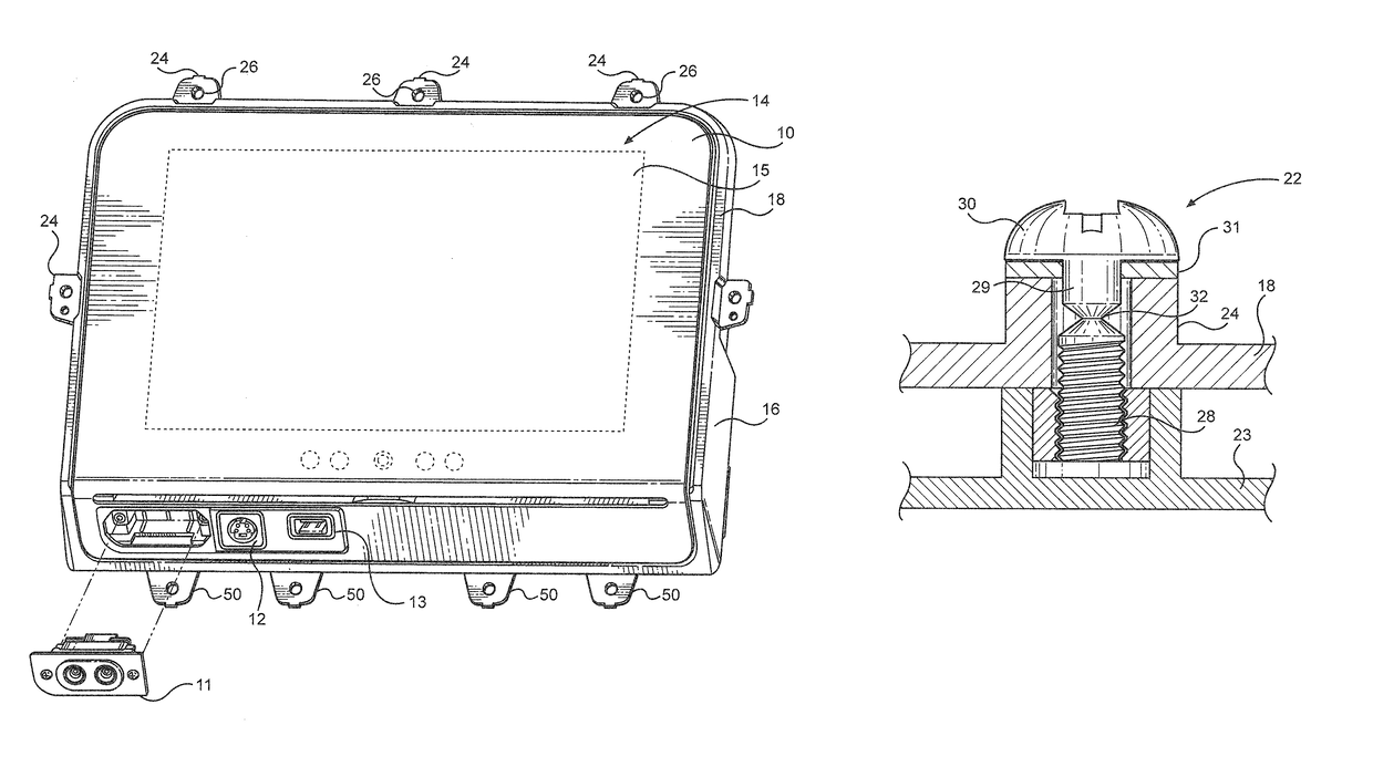
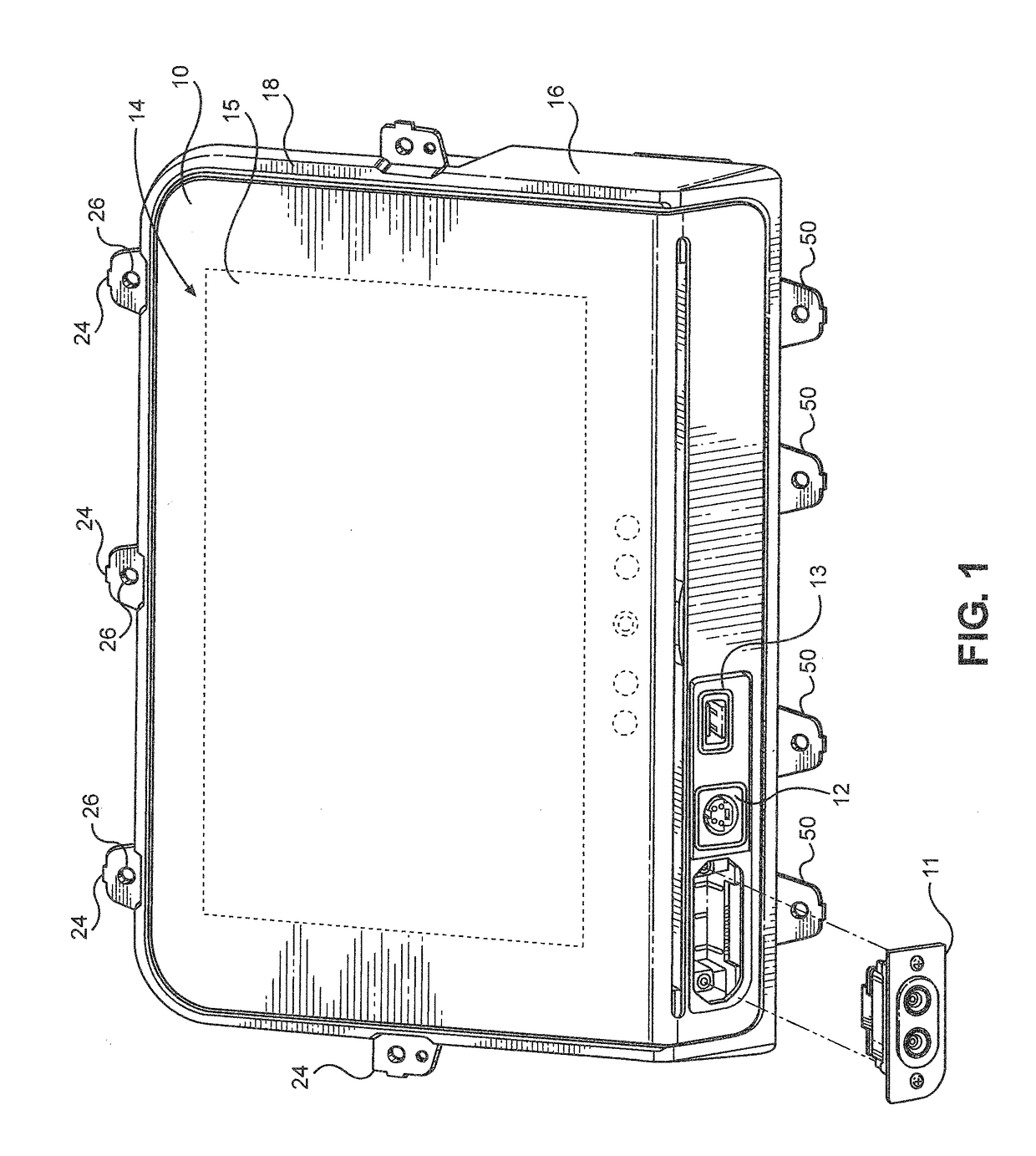
[0035]FIG. 1 illustrates a perspective, partially exploded schematic view of a preferred embodiment of a display 10 in accordance with the invention. The display 10 is for viewing by a passenger from a seat on a vehicle when the display 10 is mounted to structure in front of the passenger when the passenger is seated in the seat. The structure may be a wall or bulkhead in front of the passenger's seat or the seat back of a seat ahead of the passenger or other structure as explained in more detail in the following paragraphs. FIG. 1 illustrates the display 10 as having various types of ports 11, and 13, such as an audio jack 11 (shown removed), a personal electronic device port 12 for connecting a personal electronic device thereto, and a universal serial bus port (USB port) 13.

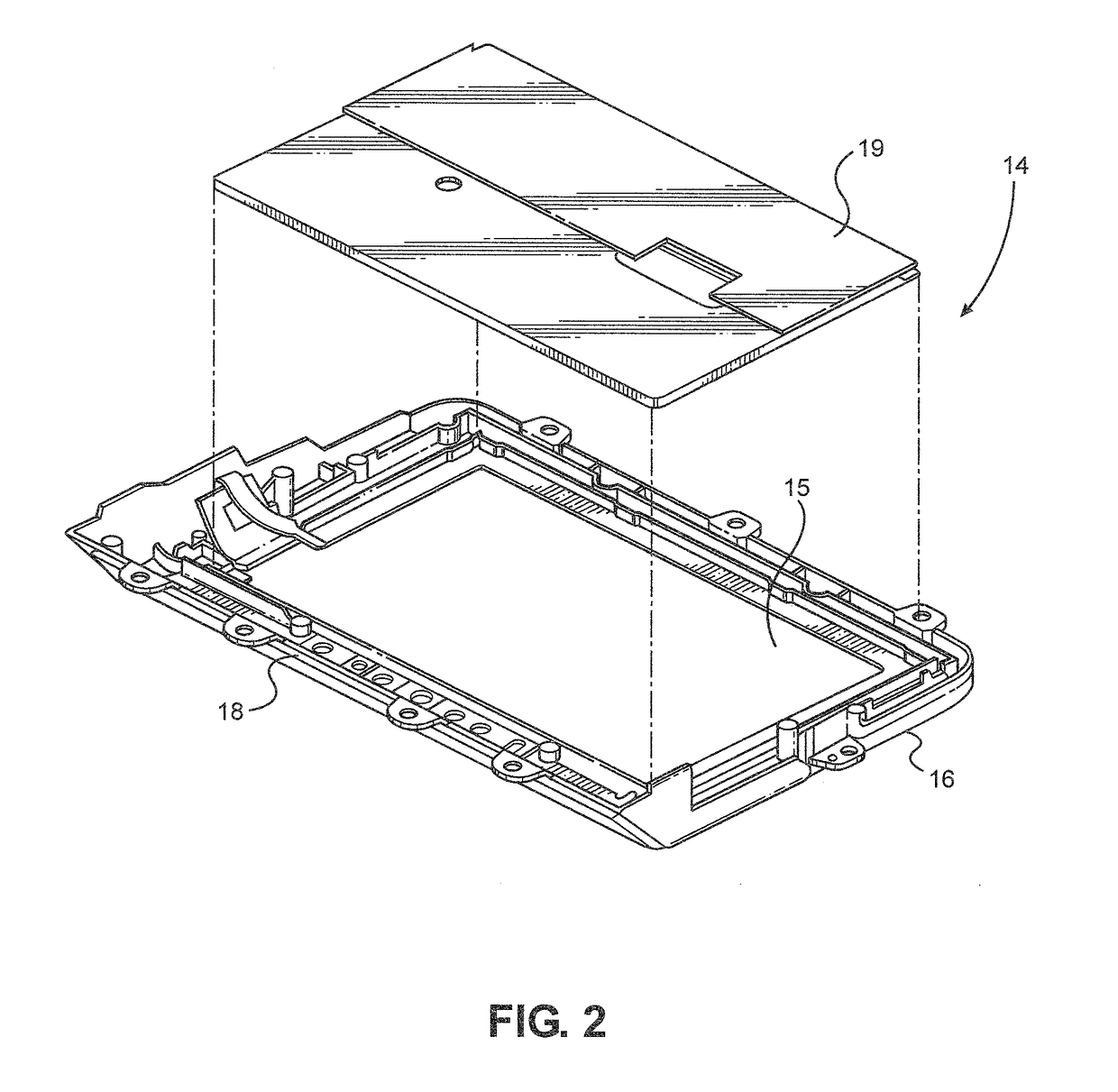
[0036]The display 10 includes an electronic visual display panel indicated generally by reference numeral 14 in FIGS. 1 and 2. The electronic visual display panel 14 includes a touch panel 15 and a liquid crys...


PUM


Abstract

A display for viewing by a passenger from a seat on a vehicle when the display is mounted to structure in front of the passenger when the passenger is seated in the seat. The structure has a recess and a portion surrounding the recess. The display includes an electronic visual display panel for receiving a display signal and displaying information in correspondence therewith to the passenger on the electronic visual display panel. The display further includes a housing in which the electronic visual display panel is mounted or inserted, with the housing including a periphery. At least one fastener is provided including a structural fuse. The structural fuse deforms and / or fractures under force generated by a passenger's head striking the visual display panel in an accident. Due to crumple of the fuse, movement of the housing is permitted, with the display panel inserted therein, relative to the recess.

Description

TECHNICAL FIELD[0001]The present invention relates generally to reducing the risk of injury to passengers in a vehicle accident, and more particularly to reducing the risk of injury to aircraft passengers in the event of an accident.BACKGROUND[0002]Passenger seats in commercial airplanes are generally arranged in rows, with one seat directly behind the other. When there is a sudden severe deceleration, a passenger is thrown forward against the lap restraint and the passenger's head moves in an arc downward and forward and usually impacts the seat back directly ahead. In the case of a seat row facing a bulkhead, the passenger's head strikes the bulkhead instead of a seat.[0003]To protect passengers from head injury, the Federal Aviation Administration (“FAA”) has established a head injury criterion (“HIC”) set forth in 14 CFR 23.562 and 25.562. The formula for HIC from the foregoing regulation is reproduced in Formula (1) below:[0004]HIC={[1t2-t1⁢∫t1t2⁢a⁡(t)⁢dt]2.5⁢(t2-t1)}max(1)Wher...

Claims


Application Information

Patent Timeline
Patent Type & Authority Patents(United States)
IPC IPC(8): B64D11/00H05K5/02B60R11/02H05K5/00B64D11/06B60N2/48F16B31/02B60R11/00B60N2/90
CPCB64D11/06B60N2/4876B60R11/0229B60R11/0235H05K5/0017H05K5/0217B60R2011/0017B60R2011/0043F16B31/021B60N2/42B60R11/02B64D25/04F16B31/00
Inventor MURATA, TSUNEYOSHICHEN, GARYYAMADA, TAKU
Owner PANASONIC AVIONICS CORP
Learn More