Gear shift mechanism

a gear shift and gear technology, applied in the direction of gearing, mechanical control devices, instruments, etc., can solve the problems of inability to adjust the gear shift, the prior art gear shift is misaligned, and the alignment of the gear shift is difficult at best, so as to simplify the hydraulic cylinder and eliminate the effect of adjustable linkages

Active Publication Date: 2017-06-06
ESKRIDGE
View PDF14 Cites 5 Cited by
  • Summary
  • Abstract
  • Description
  • Claims
  • Application Information

AI Technical Summary

Benefits of technology

[0006]The present invention achieves its objections by providing an improved gear shift mechanism which uses a hydraulic cylinder or other linear force means to push on one end of a rocker arm. This moves the rocker arm and the gear train between a first gear set and a second gear set. A biasing means is applied directly to the rocker arm by a spring or other device. Thus the present invention eliminates adjustable linkages and the need of adjustments in the field.
[0007]Further, because the biasing means in the gear drive is provided by a spring acting on the rocker arm, a simpler hydraulic cylinder can be used.

Problems solved by technology

As the gear drive is used, these linkages wear leading to misalignment of the prior art gear shift.
In extreme cases this can lead to binding and inoperability of the gear shift.
But aligning these linkages is difficult at best, especially when done by someone who is not trained to perform this task.
Further, the individual in the field would likely not have the precision measurement tools necessary to obtain a proper alignment.

Method used


Image

  • Gear shift mechanism
  • Gear shift mechanism
  • Gear shift mechanism

Examples


Embodiment Construction

)

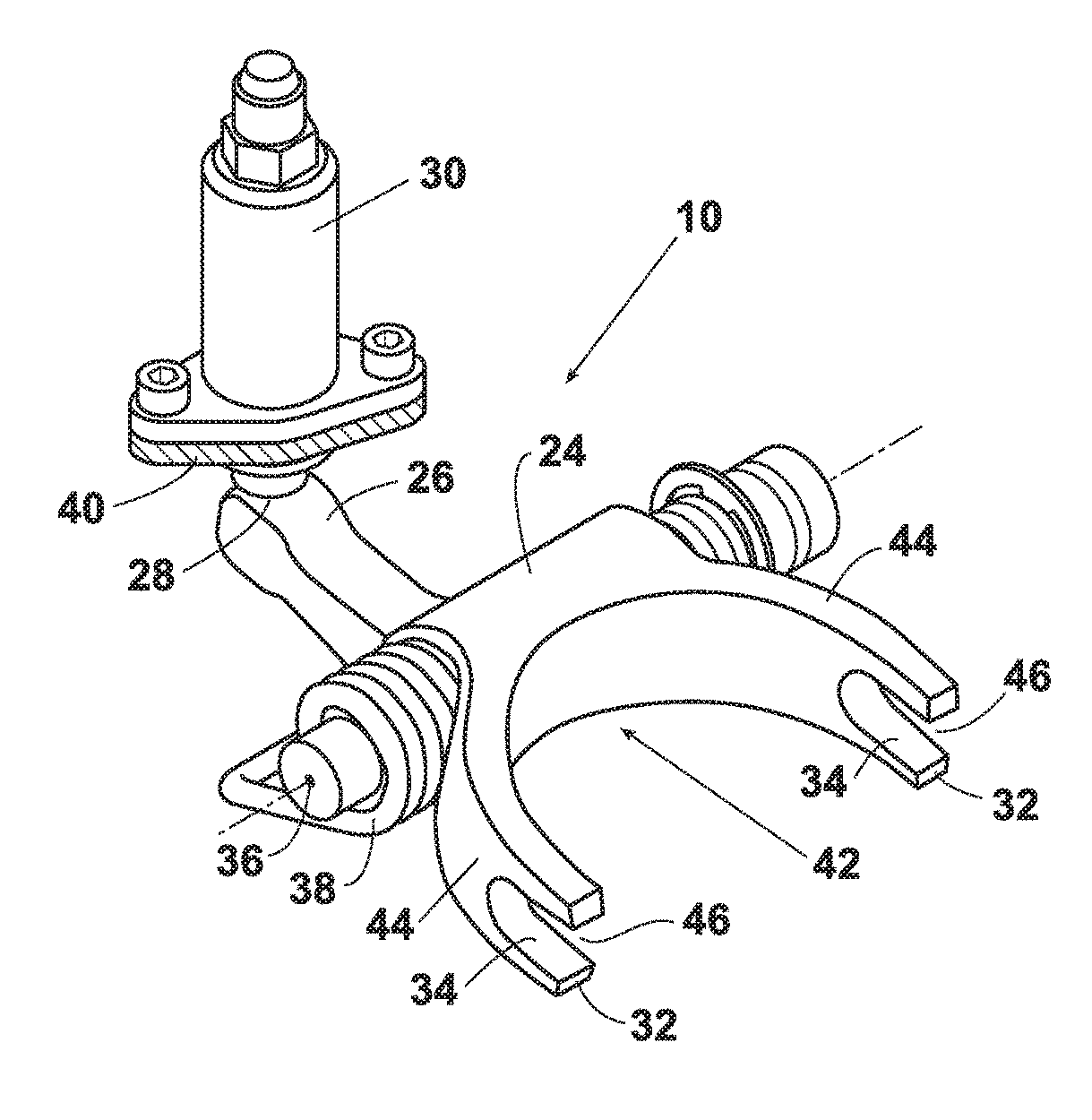
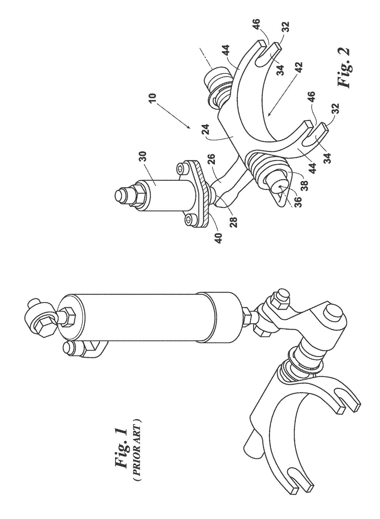
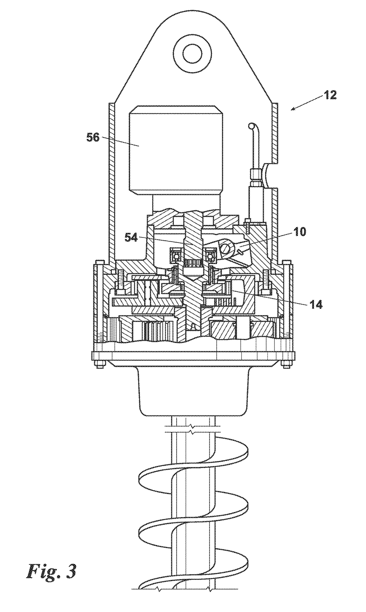
[0015]Turning now to the drawings wherein like reference characters indicate like or similar parts throughout, FIG. 2 illustrates a shifter mechanism 10 for an auger gear drive 12. The auger gear drive 12 has a planetary gear train 14 with a first planetary gear set 16 and a second planetary gear set 18 and an input gear 20 mounted on a drive spindle 22.

[0016]The shifter mechanism 10 has a rocker arm 24 pivotally mounted to the auger gear drive 12. The rocker arm 24 has a first end 26 with a contact point 28 for a linear force means 30, a second end 32 with a sliding means 34. A pivot point 36, providing the pivotal mount to the gear drive 12, is located between the first end 26 and second end 32. A biasing means 38 biases the rocker arm 24 into a first position about the pivot point 36. When the linear force means 30 is extended it contacts the contact point 28 on the rocker arm 24. This overcomes the force from the biasing means 38 and causes the rocker arm 24 to rotate about the...


PUM


Abstract

An improved gear shift mechanism for an auger gear drive which uses a hydraulic cylinder or other linear force means to push on one end of a rocker arm. This moves the rocker arm and the gear train between a first gear set and a second gear set. A biasing means is applied directly to the rocker arm by a spring or other device. The design eliminates adjustable linkages and the need adjustments in the field and allows for use of a simpler hydraulic cylinder than found in the prior art.

Description

FIELD OF THE INVENTION[0001]The present invention relates generally an improved gear shift mechanism for an auger planetary gear drive. More particularly, the present invention relates to an improved gear shift which eliminates adjustable portions of the mechanism.BACKGROUND OF THE INVENTION[0002]Multispeed planetary gear drives are commonly used to drive large earth boring augers. These augers can be used for numerous operations. They are commonly used to dig large cylindrical holes for use in setting utility poles or piers. These same gear drives are used to drill anchors and anchor foundations into the soil.[0003]These gear drives typically have two speeds or gear sets for rotating the auger. The first gear set is used when drilling under normal soil conditions. The second gear set is geared lower. That is to say one rotation of the drive motor output shaft provides more degrees of rotation when using the first gear set than when using the second gear set. Thus if operation of th...

Claims


Application Information

Patent Timeline
Patent Type & Authority Patents(United States)
IPC IPC(8): F16H3/44F16H63/32F16H3/66F16H63/04F16H63/30E21B3/02
CPCF16H63/32F16H3/66F16H63/04F16H63/3023F16H63/304E21B3/02F16H2200/2007F16H2063/3096F16H2063/325F16H2200/0034
Inventor SCHMIDTBERGER, JESSEARMSTRONG, JARED
Owner ESKRIDGE
Why Eureka
Try Eureka