Wireless power transmission device

a power transmission device and wireless technology, applied in the direction of transformer/inductance circuit, transformer/inductance details, inductance, etc., can solve the problem of not providing sufficient power transmission efficiency, and achieve the effect of improving power transmission efficiency, q factor, and improving power feeding units

Active Publication Date: 2017-06-06
TDK CORPARATION
View PDF12 Cites 1 Cited by
  • Summary
  • Abstract
  • Description
  • Claims
  • Application Information

AI Technical Summary

Benefits of technology

[0007]Accordingly, it is an object of the present invention to provide a wireless power transmission device which makes it possible to improve the Q factor in the power feeding unit that leads to an improvement in power transmission efficiency, and reduce unnecessary radiation to the surroundings and an electromagnetic influence from the surroundings.
[0009]In the wireless power transmission device according to the present invention, the distance from a surface of the feeding-side shield member which faces the feeding-side coil to a surface of the feeding-side coil which faces the feeding-side shield member is longer than the distance from a surface of the receiving-side shield member which faces the receiving-side coil to a surface of the receiving-side coil which faces the receiving-side shield member. As a result, the Q factor in the power feeding unit improves. Since power transmission efficiency is the product of a coupling coefficient k and a Q factor, the Q factor is an important factor for improving power transmission efficiency. Therefore, an improvement in Q factor leads to an improvement in power transmission efficiency. Further, because the receiving-side coil and the receiving-side shield member are disposed so as to overlap each other in the power receiving unit, unnecessary radiation to the surroundings and an electromagnetic influence from the surroundings can be reduced. Therefore, the present invention can provide a wireless power transmission device that makes it possible to both improve the Q factor in the power feeding unit which leads to an improvement in power transmission efficiency, and reduce unnecessary radiation to the surroundings and an electromagnetic influence from the surroundings.

Problems solved by technology

However, the present inventors have found as a result of diligent research that the non-contact power transmission device described in Japanese Unexamined Patent Application Publication No. 2006-42519 does not provide sufficient power transmission efficiency.

Method used


Image

  • Wireless power transmission device
  • Wireless power transmission device
  • Wireless power transmission device

Examples


first embodiment

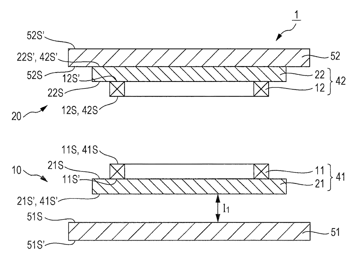
[0019]FIG. 1 is a cross-sectional view of a wireless power transmission device according to a first embodiment of the present invention.

[0020]A wireless power transmission device 1 according to the first embodiment includes a power feeding unit 10 and a power receiving unit 20 described below.

(Power Feeding Unit 10)

[0021]The power feeding unit 10 includes a feeding-side coil 41, and a feeding-side shield member 51. The feeding-side coil 41 has a primary winding 11, and a primary magnetic core 21 having two principal surfaces 215 and 21S′ that face each other. The feeding-side shield member 51 has two principal surfaces 515 and 51S′ that face each other. The principal surface 21S′ representing one of the principal surfaces of the primary magnetic core 21, and the principal surface 51S representing one of the principal surfaces of the feeding-side shield member 51 are disposed so as to face each other.

[0022]The primary winding 11 is a wire that is wound in a planar shape, and provided...

second embodiment

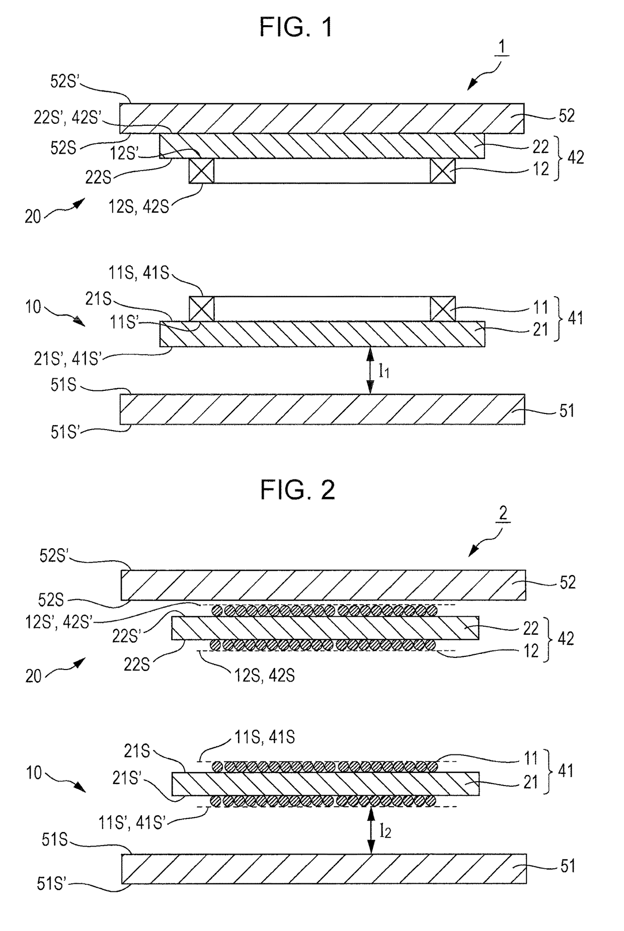
[0036]FIG. 2 is a cross-sectional view of a wireless power transmission device according to a second embodiment of the present invention.

[0037]A wireless power transmission device 2 according to the second embodiment includes a power feeding unit 10 and a power receiving unit 20 described below.

(Power Feeding Unit 10)

[0038]The power feeding unit 10 includes a feeding-side coil 41, and a feeding-side shield member 51. The feeding-side coil 41 has a primary winding 11, and a primary magnetic core 21 having two principal surfaces 21S and 21S′ that face each other. The feeding-side shield member 51 has two principal surfaces 51S and 51S that face each other. The principal surface 21S′ representing one of the principal surfaces of the primary magnetic core 21, and the principal surface 51S representing one of the principal surfaces of the feeding-side shield member 51 are disposed so as to face each other.

[0039]The primary winding 11 is a wire that is wound around the primary magnetic co...

example

[0055]Hereinafter, the present invention will be described in more detail by way of an example. However, the present invention is not limited to the example described below.

[0056]A power feeding unit was prepared by using a feeding-side coil and a feeding-side shield member described below. Further, a power receiving unit was prepared by using a receiving-side coil and a receiving-side shield member described below.

(Power Feeding Unit)

[0057]Feeding-side coil: a planar winding (primary winding) having a length of 35 cm, a width of 35 cm, and a thickness of 5 mm was bonded to one principal surface of a ferrite plate (primary magnetic core) having a length of 40 cm, a width of 40 cm, and a thickness of 2 mm.

[0058]Feeding-side shield member: an aluminum plate having a length of 40 cm, a width of 40 cm, and a thickness of 2 mm was used.

(Power Receiving Unit)

[0059]Receiving-side coil: a planar winding (secondary winding) having a length of 20 cm, a width of 20 cm, and a thickness of 5 mm ...


PUM

PropertyMeasurementUnit
thicknessaaaaaaaaaa
widthaaaaaaaaaa
lengthaaaaaaaaaa

Abstract

A wireless power transmission device includes a power feeding unit and a power receiving unit. The power feeding unit and the power receiving unit are disposed so that a principal surface of a primary magnetic core and a principal surface of a secondary magnetic core face each other across a primary winding and a secondary winding. The distance from a surface of a feeding-side shield member which faces a feeding-side coil to a surface of the feeding-side coil which faces the feeding-side shield member, is longer than the distance from a surface of a receiving-side shield member which faces a receiving-side coil to a surface of the receiving-side coil which faces the receiving-side shield member.

Description

BACKGROUND[0001]The present invention relates to a wireless power transmission device.DESCRIPTION OF THE RELATED ART[0002]A Power feeding technology which supplies power without using a power cord, that is, a so-called wireless power feeding technology has attracted attention. Since the wireless power feeding technology is able to supply power from a power feeding equipment to a power receiving equipment in a non-contact manner, it is expected to be applied to various products such as transportation equipment including electric trains and electric vehicles, household appliances, electronic equipment, wireless communication equipment, and toys.[0003]Devices used for wirelessly feeding power do not employ a system in which electricity flows from a feeding equipment side circuit to a receiving equipment side circuit by means of physical contact. Therefore, it is of vital importance for these devices to reduce the loss that occurs when transmitting electric power from the feeding equipm...

Claims


Application Information

Patent Timeline
Patent Type & Authority Patents(United States)
IPC IPC(8): H01F27/42H01F27/36H01F38/14
CPCH01F27/36H01F38/14H01F27/363
Inventor FUKUZAWA, NARUTOSHISUZUKI, MITSUNARIIL, AKIHIROSAIWAI, HIROSHI
Owner TDK CORPARATION
Why Eureka
Try Eureka