

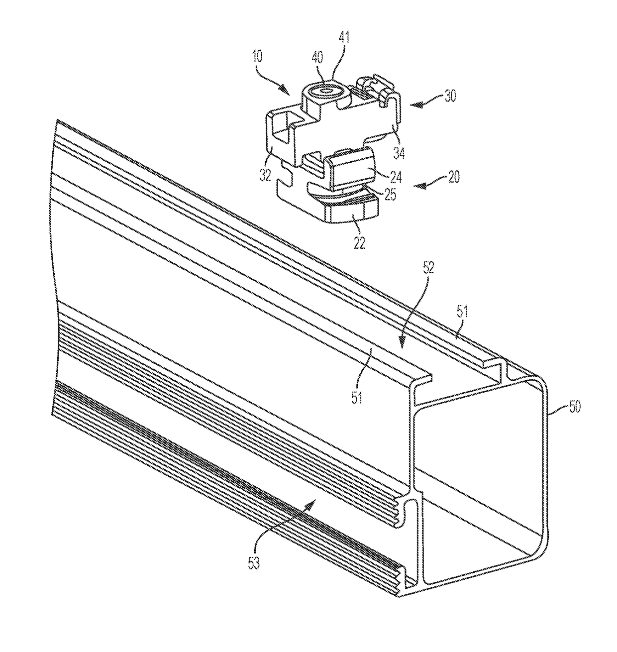
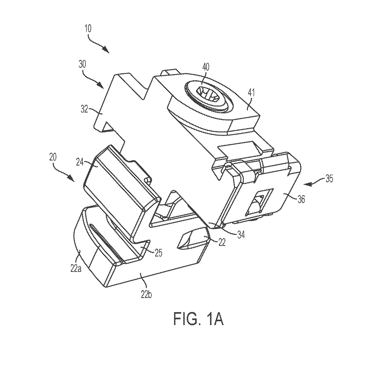
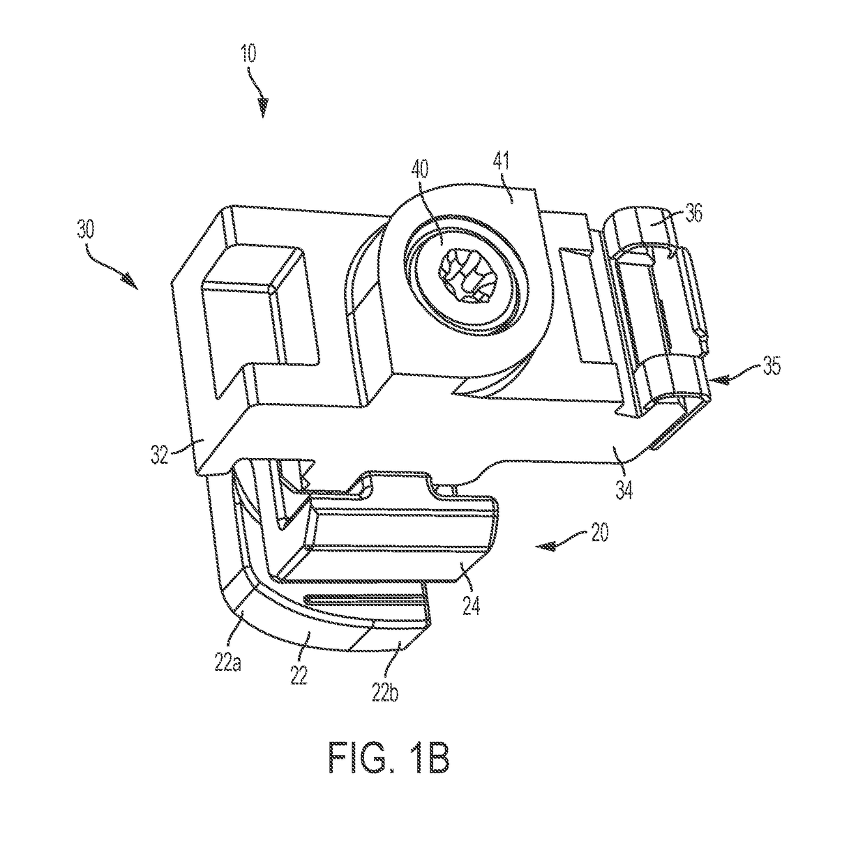
Photovoltaic mounting rail connector with drop-down connection to first photovoltaic module and slide-in connection to second photovoltaic module
a technology of photovoltaic modules and mounting rails, which is applied in the direction of connection contact members, coupling device connections, lighting and heating apparatus, etc., can solve the problems of photovoltaic modules, the installation techniques appropriate for roof structures built by relatively modern construction standards are not appropriate or safe for roof structures built according to relatively older or traditional construction standards, etc., to minimize the risk of damage to the second photovoltaic module, the effect of saving time and energy
- Summary
- Abstract
- Description
- Claims
- Application Information
AI Technical Summary
Benefits of technology
Problems solved by technology
Method used
Image

Examples
Embodiment Construction
[0020]Throughout this description for the purposes of explanation, numerous specific details are set forth in order to provide a thorough understanding of the many aspects and embodiments disclosed herein. It will be apparent, however, to one skilled in the art that the many aspects and embodiments may be practiced without some of these specific details. In other instances, known structures and devices are shown in diagram or schematic form to avoid obscuring the underlying principles of the described aspects and embodiments.
[0021]As used herein, certain terms identify the relative connections of structural element of the present system. In particular, the term “drop down” refers to a coupling of two structural elements where one structure clamps down on the other. Similarly, the term “slide-in” refers to a coupling of two structural elements where a first structure laterally moves into a receiving region of the second structure.
[0022]It can be understood that while the examples sho...
PUM
 Abstract
Description
Claims
Application Information