Electronically commutated DC motor with shielding

a technology of electromagnetic field shielding and dc motor, which is applied in the direction of shielding from electromagnetic fields, dynamo-electric machines, supports/encloses/casings, etc., can solve the problems of insufficient shielding of electrical connections to rotating rotors, insufficient shielding of components, and inability to produce electrical connections. the effect of better discharg

Active Publication Date: 2017-06-06
ROBERT BOSCH GMBH
View PDF24 Cites 0 Cited by
  • Summary
  • Abstract
  • Description
  • Claims
  • Application Information

AI Technical Summary

Benefits of technology

[0007]It is therefore the aim of the invention to create an improved DC motor of the type mentioned at the beginning of the application, which ensures with regard to the shielding a simple and less costly conductive contacting of the rotating rotor.
[0010]According to a first modification to the invention, the rotor unit comprises a metallic pole housing which is of pot-shaped design and forms the shielding; thus enabling the rotor unit itself to substantially form the shielding in this region of the motor.
[0011]In a modification to the invention which is considered to be particularly advantageous, the shaft is rotatably mounted in a first and second sintered bearing which are axially spaced apart from one another and are in each case conductively connected to the defined potential, so that two parallel capacitive couplings of the shaft to the potential result. As a result of the higher capacity, the high-frequency interferences which are generated by the motor and couple into the rotor shielding can be better discharged via the capacitive coupling to the mass potential.
[0012]According to a further modification to the invention, a metal plate connected to the defined potential is provided for further shielding the motor in the axial direction that is opposite the shielding of the rotor unit. The metal plate is disposed on the end face of the stator unit that faces away from the rotor unit and is conductively connected via a connection means to at least one sintered bearing in order to produce the capacitive coupling. In so doing, the complete shielding of the motor is made possible.
[0013]Because it is evident from measurements, that it is more favorable to use at least the upper first sintered bearing, which is arranged in the region of the end face of the stator unit that faces the rotor unit, for capacitive coupling, it is advantageous for the connection means to comprise a pin that is preferably integrally connected to the metal plate and extends in the axial direction from the metal plate through the stator unit into the region of the end face thereof which faces the rotor unit. The aforementioned pin opens up the possibility of a simple contacting of the upper sintered bearing. In a modification to this embodiment, said pin is encased with a dome-shaped plastic overmold in the proximity of the free end thereof, so that moisture cannot penetrate into the motor from the free end thereof.
[0014]Besides the rotor unit, a fan wheel is fastened to the shaft in a rotationally fixed manner; thus enabling the DC motor to be designed or used as a fan motor comprising integrated commutating electronics.

Problems solved by technology

These radiated waves can be measured within the scope of EMC tests and are undesirable in many technical environments, for example in motor vehicles, which include other electrical devices that are susceptible to interference.
In order to achieve an effective shielding, it is not sufficient to surround the components to be shielded with conductors.
Otherwise, in the worst case, the shielding itself can couple or decouple high-frequency energy while functioning like an antenna and thereby worsen the interference problem.
The electrical connection to the rotating rotor shielding required here is however not easily produced.
It can, in fact, occur in a known manner via a sliding contact, which however requires additional components and presents a problem with regard to service life.

Method used


Image

  • Electronically commutated DC motor with shielding
  • Electronically commutated DC motor with shielding
  • Electronically commutated DC motor with shielding

Examples


Embodiment Construction

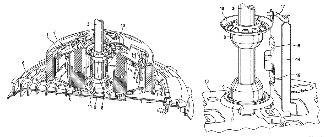
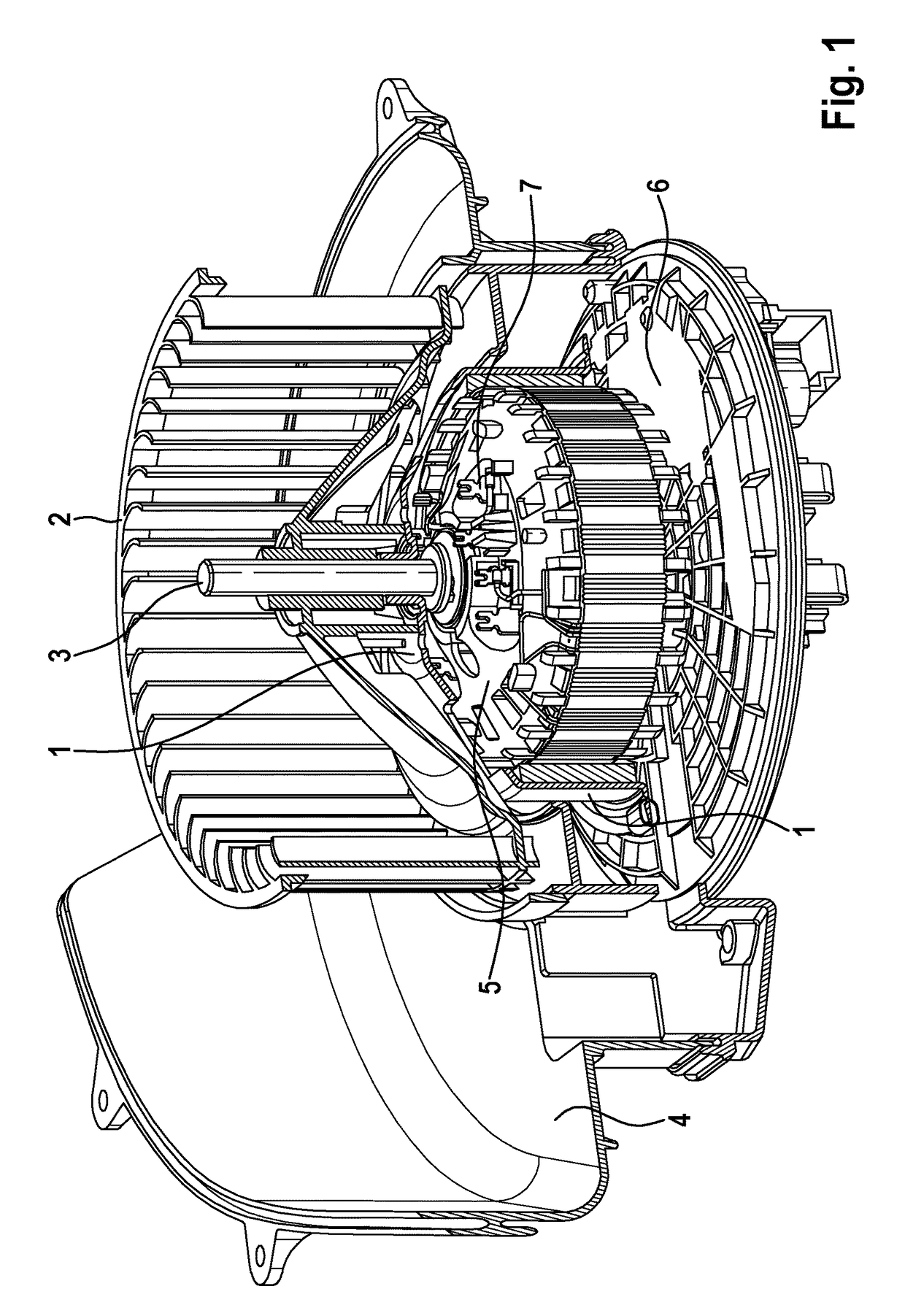
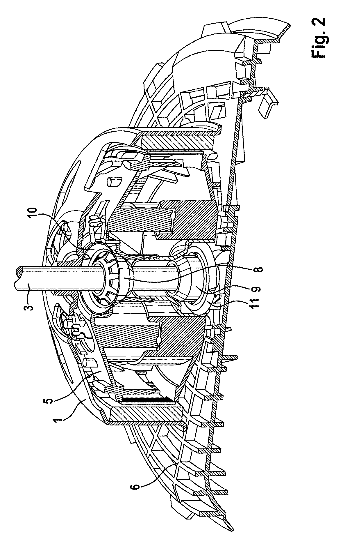
[0022]A cross section through the air duct 4 of an exemplary embodiment of the DC motor is depicted in FIG. 1. A preferred application of the DC motor of flat design is the use as a fan for the air conditioning unit of a motor vehicle. To this end, a relevant fan wheel 2 is fastened to the rotating shaft 3, said fan wheel drawing in air via the air duct 4 from the exterior area of the vehicle. The rotor unit 1, which is likewise disposed on the shaft 3 in a rotationally fixed manner, consists of a metallic pole housing which is designed in a pot-shaped manner and on the interior of which magnets are fastened that interact with the coils of the stator unit 5 in a manner know per se during the operation of the electric motor, said stator unit being disposed in the pot of the rotor unit 1 and fastened to the housing flange 6. The mounting of the rotating shaft 3 in a first and second sintered bearing 8 or respectively 9, which are axially spaced apart from one another at a distance cor...


PUM


Abstract

In an electronically commutated DC motor having a stator unit (5) and a rotor unit (1) which is in the form of an external rotor, and having stationary sintered bearings (8, 9), the invention proposes that the rotor unit (1) is conductively connected to the shaft (3) in order to connect a conductive shielding, which is formed on the rotor unit (1), to a defined electrical potential, and that the sintered bearing (8, 9) is conductively connected to the potential, so that the shielding of the rotor unit (1) is capacitively coupled to the potential by means of the electrically insulating, oil-filled bearing gap which is arranged between the shaft (3) and the sintered bearing (8, 9). Therefore, a sliding contact is not required.

Description

BACKGROUND OF THE INVENTION[0001]The invention relates to a DC motor having a stator unit and a rotor unit, which is connected to an electrically conductive shaft in a rotationally fixed manner, said shaft being rotatably mounted in at least one stationary sintered bearing. The DC motor also has a shielding for protection against high-frequency electromagnetic fields.[0002]A generic DC motor is known, for example, from the German patent application DE 1 638 216 A1. It is also thereby known to provide a metal plate, which is electrically connected to ground, on the end face of the stator unit which is opposite the rotor unit, i.e. in the region of a base plate or mounting plate of the stator unit, in order to provide shielding in this axial direction.[0003]The present invention is based on a brushless, electronically commutated DC motor (EC=electrically commutated or BLDC=brushless direct current) of flat construction in which the axial expansion of the motor is therefore small in re...

Claims


Application Information

Patent Timeline
Patent Type & Authority Patents(United States)
IPC IPC(8): H02K11/02H02K11/22H02K11/01H02K11/40H02K5/16
CPCH02K11/022H02K5/16H02K11/01H02K11/40H02K11/0141
Inventor ROTHFUSS, TOBIASMAELZER, MICHAELMUNZ, JUERGENHERMANN, MICHAELPRAHL, DETLEFSCHOSER, SIEGMARBRANDES, JOERGSCHIEL, ANDREASBANKY, TAMASDUDAS, ZSOLT
Owner ROBERT BOSCH GMBH
Why Eureka
Try Eureka