Bullpup firearm conversion system

a conversion system and bullpup technology, applied in the field of bullpup firearm conversion systems, can solve the problems of long pull length, inferior trigger pull characteristics of the host firearm, and traditional bullpup designs, and achieve the effects of reducing pull length, shortening pull length, and improving one-handed operation

Inactive Publication Date: 2017-06-13
VANKEUREN III LEWIS KARL
View PDF25 Cites 19 Cited by
  • Summary
  • Abstract
  • Description
  • Claims
  • Application Information

AI Technical Summary

Benefits of technology

[0007]An advantage of the present invention is achieved by providing a uniquely designed buttstock resulting in a reduced pull length; a forwardly sloping butt design achieves a shorter pull length by allowing the upper portion of the butt to rest on the shoulder or upper arm of the user, thus improving one-handed operation.
[0008]Due to the rearward placement of the firearm action relative to the butt in a bullpup configured firearm, a mechanism that places an auxiliary cocking handle forward of the action and in operational communication with the firearm's original cocking handle is a desirable feature. Also, due to the rearward placement of the firearm action relative to the butt in a bullpup configured firearm, the original sights cannot be used. Thus, it is desirable to provide auxiliary sights or an attachment platform for auxiliary sights.
[0009]Another advantage is achieved by connecting the auxiliary sights and / or the attachment platform for the auxiliary sights directly to the firearm receiver, because doing so provides a more stable and therefore accurate arrangement.
[0010]Yet another advantage is achieved by combining the aforementioned auxiliary cocking handle and attachment platform for auxiliary sights into an assembly that is connected directly to the receiver. This arrangement achieves the aforementioned advantages as well as requiring less volume and mass than would be needed for the separate components.
[0011]In the various embodiments described, the present invention is advantageous in that it requires minimal gunsmithing knowledge or mechanical expertise to install, provides a configuration that conforms to the shoulder or upper arm and places the firearm action close to the body and shortens the pull length, provides an auxiliary trigger forwardly positioned in front of the action and the magazine, provides a an auxiliary cocking handle forwardly positioned in front of the action, and provides a stable mounting platform for auxiliary sights.
[0012]In one embodiment, a bullpup conversion system comprises, a grip adapted to be gripped by a user in such a way so as to allow the user to engage an auxiliary trigger; a trigger linkage mechanism operatively engaging the auxiliary trigger and a first trigger of a barreled action, wherein the linkage mechanism includes a cable; the grip and auxiliary trigger being located in front of the barreled action; a trigger safety for restraining the auxiliary trigger in a non-firing position; a butt having a rearwardly oriented surface adapted to conform to the upper surface of the operator's shoulder-upper arm region; a sight and / or scope accessory mounting rail; a cocking handle linkage mechanism having an auxiliary cocking handle for operatively engaging a first cocking handle; wherein the sight and / or scope accessory mounting rail and cocking handle linkage mechanism comprise an assembly (aka a combined system); the foregoing enclosed within a two piece chassis system. It is to be understood that the term “chassis”, as used herein, is interchangeable with, and in the nature of, an “enclosure” and thus is not limited in meaning to a frame or subframe.

Problems solved by technology

The trigger pull characteristics of these mechanisms is generally considered inferior to the trigger pull characteristics of the host firearm.
However, traditional bullpup designs are problematic in that the pull length is too long for efficient one-handed operation.
Also, due to the rearward placement of the firearm action relative to the butt in a bullpup configured firearm, the original sights cannot be used.

Method used


Image

  • Bullpup firearm conversion system
  • Bullpup firearm conversion system
  • Bullpup firearm conversion system

Examples


Embodiment Construction

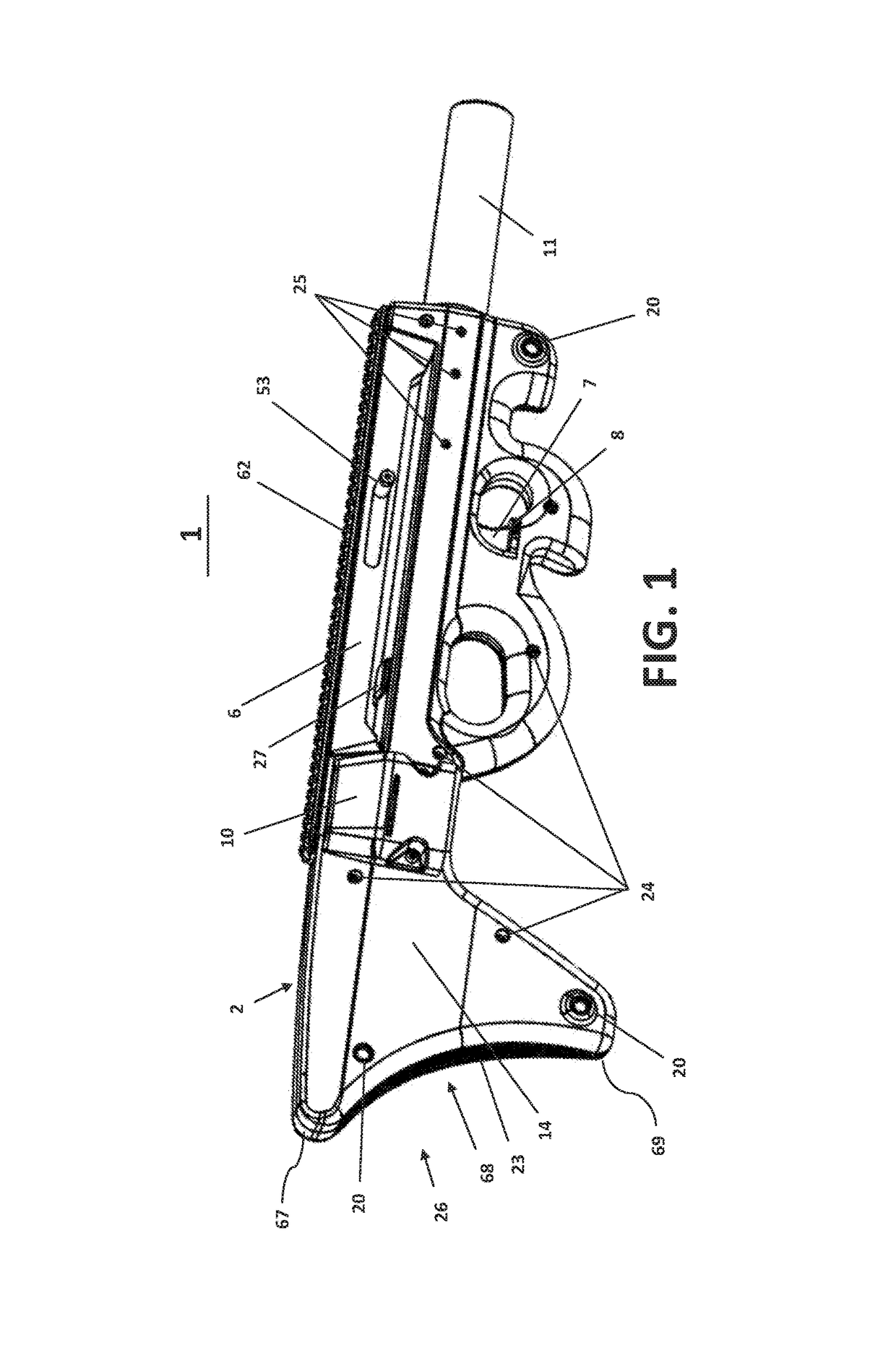
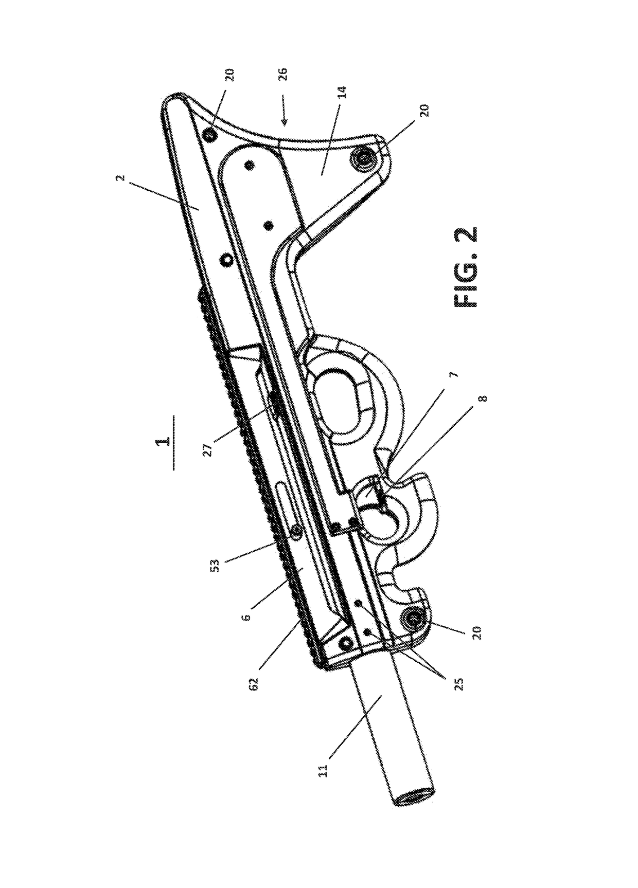
[0094]Turning now to the drawings in which like reference characters indicate corresponding elements throughout the several views, as used herein, the word “front” or “forward” corresponds to where the muzzle end of the barrel is located (i.e., to the right as shown in FIGS. 1, and 3 through 6, and to the left in FIG. 2); “rear” or “rearward” or “back” corresponds to the direction opposite where the muzzle end of the barrel is located (i.e., to the left as shown in FIGS. 1, and 3 through 6, and to the right in FIG. 2).

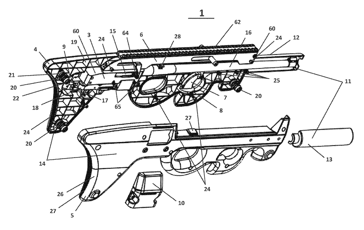
[0095]As shown in FIGS. 1-3, the present invention is directed to a bullpup stock kit, designated by reference numeral 2, for use with the barreled action 3 of a rifle. The combination of the barreled action 3 and the bullpup stock kit 2 is referred to as the bullpup configured firearm, or simply bullpup, and is designated by reference number 1.

[0096]Best shown in the exploded view of FIG. 3, the bullpup stock kit 20 comprises a left stock body portion 4, a right stock...


PUM


Abstract

A firearm bullpup conversion system incorporates a uniquely configured buttstock that conforms to the operator's shoulder or upper arm to reduce the pull length for a given overall stock length. The system also provides for an auxiliary trigger located in front of the action, an integrated cocking and accessory mounting rail, and a trigger safety.

Description

BACKGROUND AND SUMMARY[0001]This invention relates generally to firearms, and more particularly to stock or conversion kits (a.k.a. “bullpup stock kit”, “bullpup stock system”) which convert a traditional firearm into bullpup configurations.[0002]Firearm “bullpup” configurations are discussed in some detail in Wikipedia, some portions paraphrased, summarized, and or quoted herein. Traditionally, firearms using detachable magazines are configured so that fee action of the firearm and fee ammunition magazine are located in front of the trigger. Firearms configured so that the action and the magazine are located behind the trigger of fee firearm are generally referred to as “bullpups”.[0003]Bullpup configuration permits a shorter overall weapon for a given barrel length. This is due to the positioning of the action closer to the rear end of the buttstock. This maintains the advantages of a longer barrel in muzzle velocity and accuracy, while improving maneuverability and reducing weigh...

Claims


Application Information

Patent Timeline
Patent Type & Authority Patents(United States)
IPC IPC(8): F41C23/20F41A19/10F41A19/09F41A17/46
CPCF41C23/20F41A17/46F41A19/10F41A19/09F41A3/72F41C23/00F41C23/12
Inventor VANKEUREN, III, LEWIS KARL
Owner VANKEUREN III LEWIS KARL
Why Eureka
Try Eureka