
Control system for vehicle

a control system and vehicle technology, applied in the direction of electric control, engine starters, machines/engines, etc., can solve the problems of driver stress type, and achieve the effects of less likely to suffer shock, short required time, and faster respons

Active Publication Date: 2017-06-27
TOYOTA JIDOSHA KK
View PDF27 Cites 3 Cited by
  • Summary
  • Abstract
  • Description
  • Claims
  • Application Information

AI Technical Summary

Benefits of technology

[0009]Embodiments of the present invention reduce a delay in starting, while suppressing vibration of a vehicle caused by pre-ignition.
[0027]Generally, the transition of the clutch from the engaged state to the released state is completed in a shorter required time, with quicker response, and is less likely to suffer from shock at the time of switching, as compared with the transition from the released state to the engaged state. Accordingly, as in the above arrangement, it is advantageous to place the clutch in the engaged state while the internal combustion engine is stopped after being automatically stopped.

Problems solved by technology

On the other hand, in the vehicles of JP 2001-020769 A and JP 2011-208699 A, since the engine is automatically started while the clutch is placed in the released state, a time lag for transition of the clutch from the released state to the engaged state arises after the engine is started, and the delay in starting may place another type of stress on the driver.

Method used


Image

  • Control system for vehicle
  • Control system for vehicle
  • Control system for vehicle

Examples


first embodiment

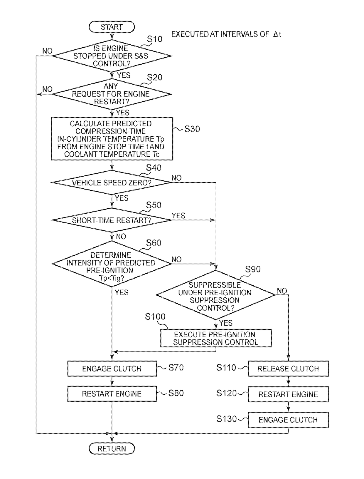
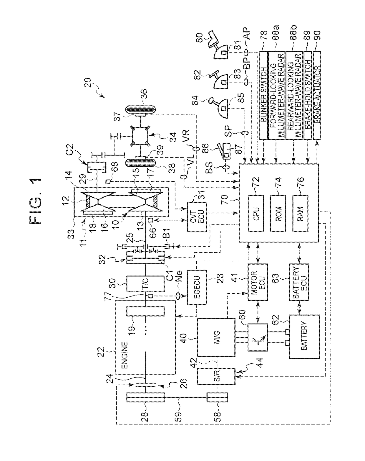
[0054]The engine 22 is automatically stopped by stopping fuel injection and stopping supply of electric power to ignition plugs, and the engine 22 is restarted by restarting fuel injection and supply of electric power to the ignition plugs, and driving the motor-generator 40. The S&S control is performed when the vehicle is decelerated after warm-up is completed, for example, for improvement of the fuel economy and reduction of emissions. During execution of the S&S control, if the engine 22 is automatically stopped under S&S control, an S&S control execution flag indicating that the S&S control is being executed is set, (the S&S control execution flag will be described later) in the following automatic start control. Further, in the first embodiment, the forward / reverse switching mechanism 32 is controlled to be held in the engaged state, while the engine 22 is stopped after it is automatically stopped under S&S control.

[0055]Also, in the vehicle 20, when the brake-hold switch 89 a...

second embodiment

[0092]In the second embodiment, even when the braking force is held constant under the brake hold control (an affirmative decision (YES) is obtained in step S250), the predicted response control (steps S310-S370) is executed in the case where the direction indicator is ON (step S260), the case where the accelerator depression amount is smaller than the ON value Dstart as an automatic start condition (step S270), and the case where the distance to an obstacle present in the travelling direction is smaller than the predetermined value (step S280). Accordingly, in these cases where stress placed on the driver by vibration of the vehicle in the starting direction is relative large, pre-ignition is more likely to be avoided.

[0093]By releasing any of other clutches provided in the power transmission path from the engine 22 to the drive wheels 36, 38, for the same purpose, in place of the forward / reverse switching mechanism 32, power transmission from the engine 22 to the drive wheels 36, ...


PUM


Abstract

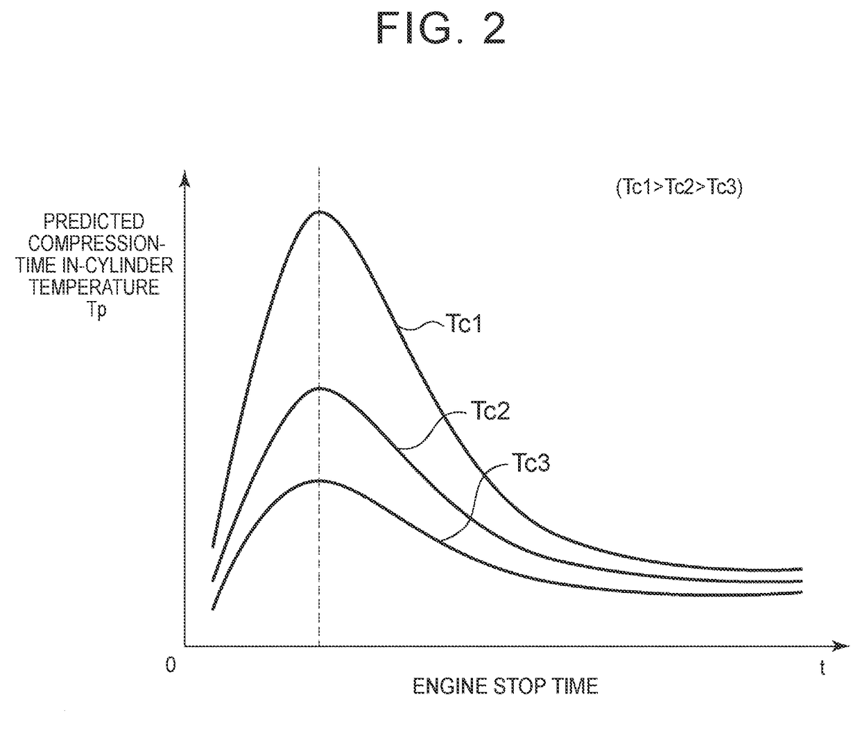
If a predicted compression-time in-cylinder temperature Tp having a positive correlation with the intensity of predicted pre-ignition is equal to or higher than a pre-ignition threshold value Tig when a request for automatic start is made, a forward / reverse switching mechanism is placed in a released state, and an engine is automatically started. If the predicted compression-time in-cylinder temperature Tp is lower than the pre-ignition threshold value Tig, the forward / reverse switching mechanism is placed in an engaged state, and the engine is automatically started.

Description

INCORPORATION BY REFERENCE[0001]The disclosure of Japanese Patent Application No. 2015-001475 filed on Jan. 7, 2015 including the specification, drawings and abstract is incorporated herein by reference in its entirety.BACKGROUND OF THE INVENTION[0002]1. Field of the Invention[0003]Embodiments of the present invention relates to a control system for a vehicle having a function of automatically stopping and automatically starting an internal combustion engine during running, so as to save fuel or reduce exhaust emissions.[0004]2. Description of Related Art[0005]A control system for a vehicle, which performs automatic stop-and-restart control on an engine, has been proposed. The system automatically stops the engine under given stop conditions, when an automobile stops at an intersection, for example, and restarts the engine under given restart conditions, when the accelerator pedal is depressed, for example. Generally, the engine is automatically stopped when the vehicle is stopped. ...

Claims


Application Information

Patent Timeline
Patent Type & Authority Patents(United States)
IPC IPC(8): B60W30/20B60W10/06B60W30/18B60W10/02B60W20/00F02D41/06F02N11/08F02D35/02B60W20/40F02N11/04F02D41/02
CPCB60W30/18054B60W10/02B60W10/06B60W20/00B60W20/40B60W30/18B60W30/20F02D35/026F02D41/065F02N11/0814F02N11/0825F02N2200/0802F02N2200/101F02N2200/12Y02T10/48B60W2030/206B60W2550/10B60W2560/06B60W2710/021B60W2710/06B60W2710/0622F02D41/022F02D2200/021F02N11/04F02N2011/0896F02N2200/0801B60W2510/06B60W2510/0676B60W2520/04B60W2520/06B60W2540/10B60W2540/12B60W2540/20B60W30/18027F02D29/02F02D2200/50B60W2530/213B60W2554/00Y02T10/40B60W2710/022B60W2520/10B60W50/0097B60W10/00
Inventor FURUYA, YOSHIHIRO
Owner TOYOTA JIDOSHA KK
Learn More