
Device and method for controlling urea injection system of diesel engine

a technology of urea injection system and diesel engine, which is applied in the direction of engine components, mechanical equipment, machines/engines, etc., can solve the problems of direct affecting the conversion rate of oxynitride in the engine post-treatment scr system, and achieve the effect of accurate urea injection pressure, fast system response and reduced deviation

Active Publication Date: 2017-06-27
WEICHAI POWER CO LTD
View PDF9 Cites 1 Cited by
  • Summary
  • Abstract
  • Description
  • Claims
  • Application Information

AI Technical Summary

Benefits of technology

This patent describes a control system for a urea injection system in a diesel engine. The system uses a physical model to accurately control the injection of urea into the engine. This model takes into account various operating conditions, resulting in a faster and more accurate response of the system. This control system reduces the deviation between the actual urea pressure and the target pressure, minimizing the calibration workload and improving efficiency and functionality of the system. Overall, this approach ensures a more effective and dependable control of the engine's urea injection system.

Problems solved by technology

However, as compared with the gasoline engine with the same power, the diesel engine emits particulates and oxynitride which are two most major pollutants in the exhaust gas.
Besides, based on the existing PID control policy and in some operation conditions of an engine, there would a large deviation between an actual value and the target value of the urea pressure, which causes a relatively larger deviation between an actual injection amount of urea and a target urea injection amount in the urea injection system, which therefore directly affects conversion rate of oxynitride in the engine post-treatment SCR system.

Method used


Image

  • Device and method for controlling urea injection system of diesel engine
  • Device and method for controlling urea injection system of diesel engine
  • Device and method for controlling urea injection system of diesel engine

Examples


Embodiment Construction

[0026]Hereinafter, an apparatus and method for controlling a urea injection system of a diesel engine as provided by the present invention will be depicted in detail through embodiments with reference to the accompanying drawings. It should be understood that these embodiments are provided only to enable those skilled in the art to better understand and further implement the present invention, not intended for limiting the scope of the present invention in any manner.

[0027]Additionally, the term “operation condition parameter” used herein indicates any value that can indicate a physical quantity of the (target or actual) physical state or operation condition of the engine. Moreover, in the context of this specification, term “parameter(s)” may be used interchangeably with the physical quantity represented thereby. For example, “a parameter indicating urea flow” has an equivalent meaning herein with “urea flow.”Moreover, in the context of the present specification, suppose P denotes ...


PUM


Abstract

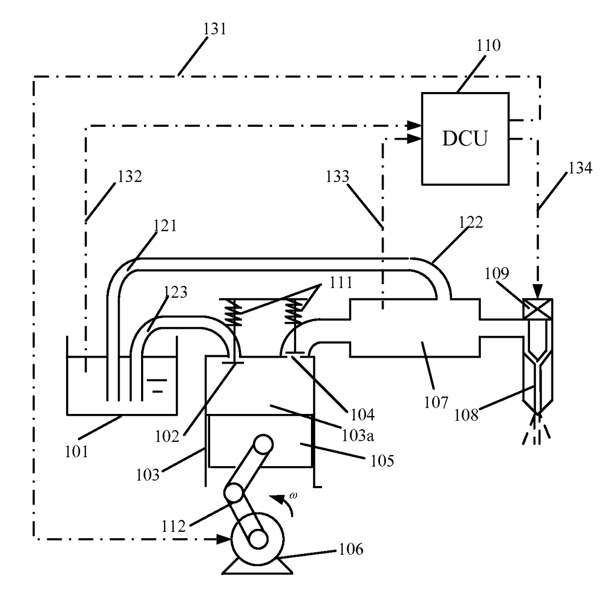
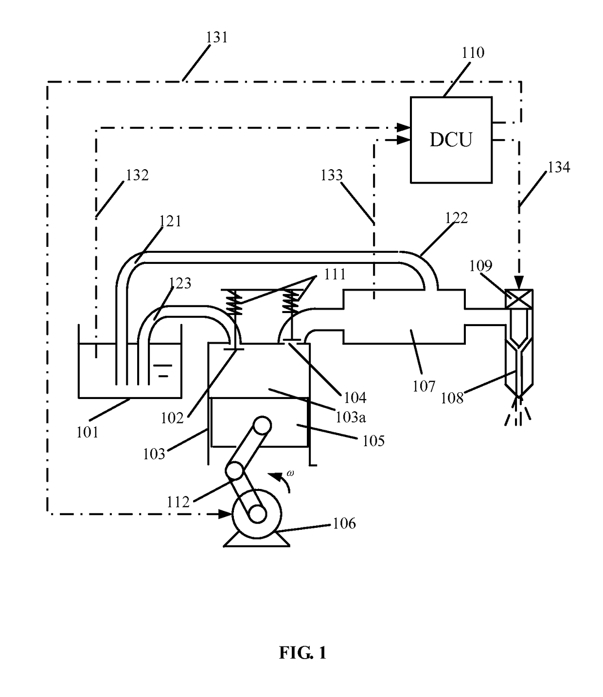
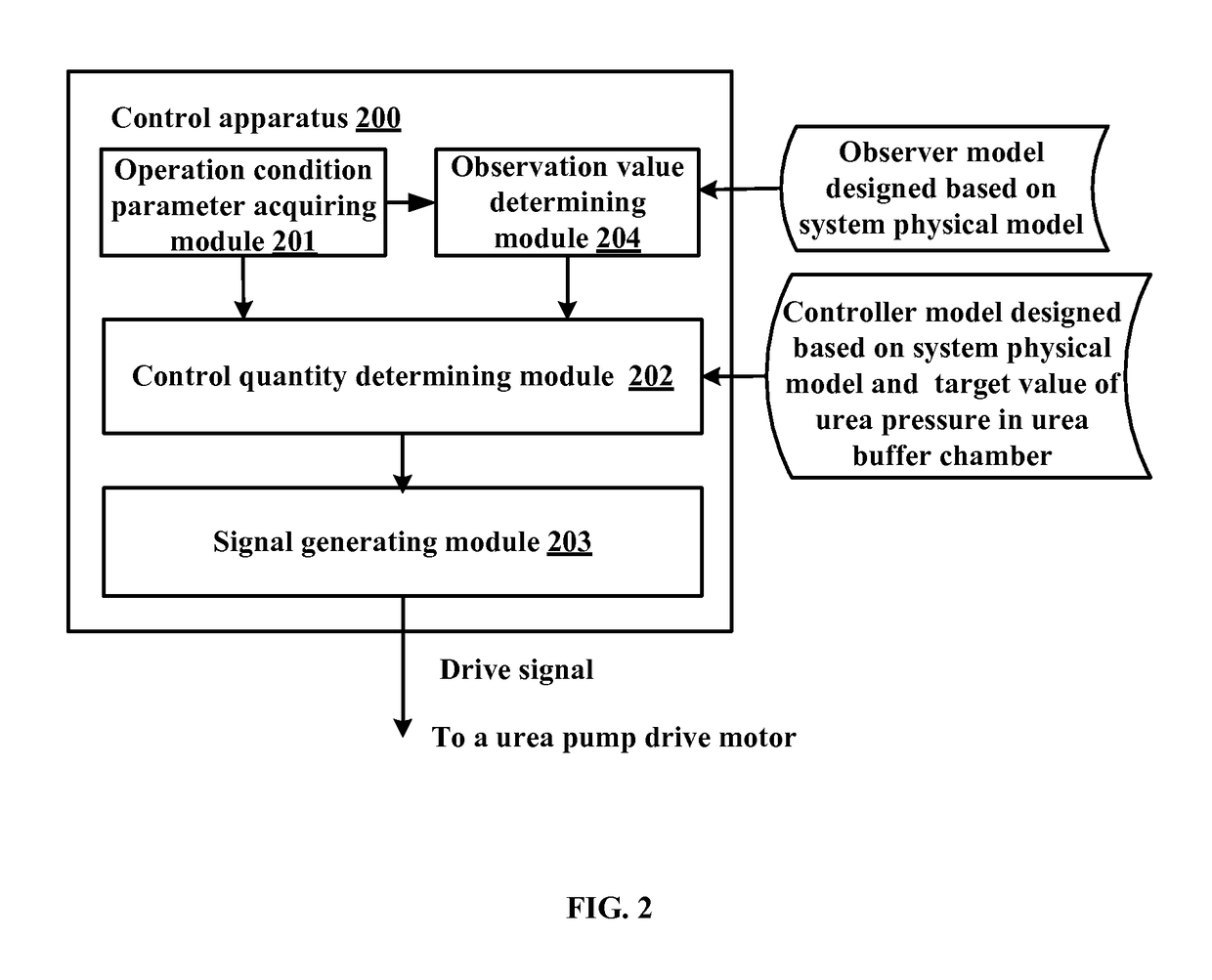
Disclosed are an apparatus and a method for controlling a urea injection system of a diesel engine. The apparatus (200) comprises: an operation condition parameter acquiring module (201), a control quantity determining module (202) and a drive signal determining module (203), wherein the operation condition parameter acquiring module (201) is configured to acquire operation condition parameters related to the urea injection system, the control quantity determining module (202) is configured to determine a control quantity for controlling the urea injection system based on the operation condition parameters, a target value of urea pressure in a urea buffer chamber (107) and a control model designed based on a physical model of the urea injection system, and the drive signal determining module (203) is configured to determine a drive signal for a urea pump (103) drive motor (106) according to the determined control quantity. The method for controlling the urea injection system may achieve accurate control of the urea injection pressure, and reduce a deviation between the urea pressure and a target value of the urea pressure.

Description

FIELD OF THE INVENTION[0001]The present invention generally relates to the technical field of diesel engines, and more specifically, relates to an apparatus and method for controlling a urea injection system of a diesel engine.BACKGROUND OF THE INVENTION[0002]Since diesel engines come into being, they have been widely applied in various propulsion installation, ships and vehicles due to their advantages such as excellent dynamic performance, cost-effectiveness and durability. Compared with gasoline engines, diesel engines have many advantages: reduced exhaust gas emission, better acceleration performance at a lower vehicle speed, lower average fuel consumption, and more driving fun. However, as compared with the gasoline engine with the same power, the diesel engine emits particulates and oxynitride which are two most major pollutants in the exhaust gas.[0003]At present, a technology for reducing vehicle exhaust gas emission to meet an emission standard usually employs an exhaust ga...

Claims


Application Information

Patent Timeline
Patent Type & Authority Patents(United States)
IPC IPC(8): F01N3/00F01N3/20F01N9/00F01N3/10
CPCF01N3/10F01N3/208F01N9/00F01N2610/02F01N2610/146F01N2900/1808F01N2900/1812Y02T10/24Y02T10/47Y02T10/12Y02T10/40
Inventor HU, GUANGDISUN, SHAOJUNTONG, DEHUIGUO, SHENGGANGSUN, YONGLIANG
Owner WEICHAI POWER CO LTD
Learn More