Driver and electronic device

a technology of electronic devices and drivers, applied in the direction of instruments, static indicating devices, etc., can solve the problems of increasing power consumption of drivers, reducing the time a driver drives a single pixel, and reducing the power consumption of drivers

Active Publication Date: 2017-07-04
SEIKO EPSON CORP
View PDF19 Cites 2 Cited by
  • Summary
  • Abstract
  • Description
  • Claims
  • Application Information

AI Technical Summary

Benefits of technology

[0031]Through this, the electro-optical panel can be driven through phase expansion driving. Phase expansion driving can drive many source lines with few data line driving circuits, and thus the driver can be reduced in size. On the other hand, the number of instances of driving for displaying a single frame of an image increases, and thus high-speed driving is necessary. According to this aspect of the invention, high-speed driving can be realized through capacitive driving, and thus electro-optical panels having higher resolutions can be driven.

Problems solved by technology

Increases in the resolutions of such display devices continue to progress, and as a result, the time a driver drives a single pixel is becoming shorter.
However, with the increases in resolutions of electro-optical panel as mentioned above, it is becoming difficult for the amplifier circuits to finish writing the data voltages within the required time.
Achieving both requires, for example, an increase in the bias voltage of the amplifier circuits, resulting in a further increase in power consumption in drivers as increases in resolution progress.
Accordingly, there is a problem in that output voltages will vary depending on a connection environment of the driver (the type of the electro-optical panel connected to the driver, the design of a printed circuit board on which the driver is mounted, and so on, for example).

Method used


Image

  • Driver and electronic device
  • Driver and electronic device
  • Driver and electronic device

Examples


Embodiment Construction

[0049]Hereinafter, preferred embodiments of the invention will be described in detail. Note that the embodiments described hereinafter are not intended to limit the content of the invention as described in the appended claims in any way, and not all of the configurations described in these embodiments are required as the means to solve the problems as described above.

[0050]1. First Example of Configuration of Driver

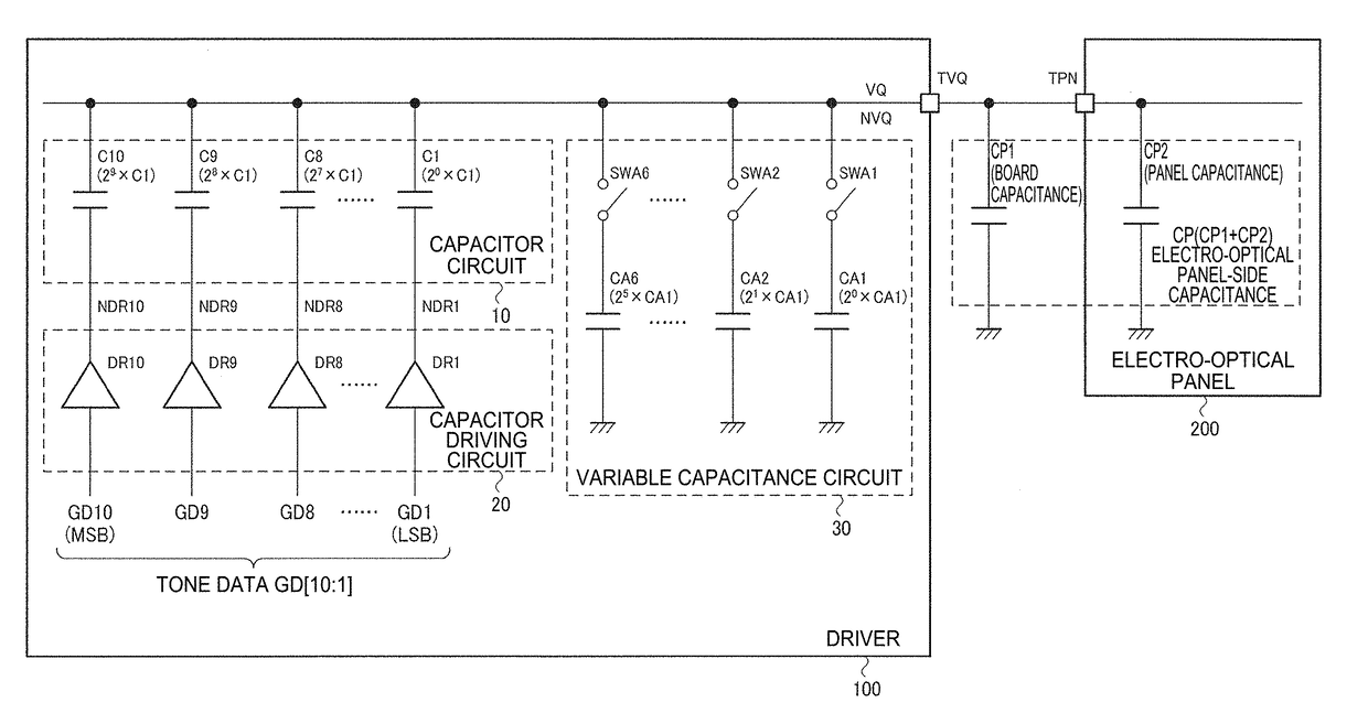
[0051]FIG. 1 illustrates a first example of the configuration of a driver according to this embodiment. This driver 100 includes a capacitor circuit 10, a capacitor driving circuit 20, and a data voltage output terminal TVQ. Note that in the following, the same sign as a sign for a capacitor is used as a sign indicating a capacitance value of that capacitor.

[0052]The driver 100 is constituted by an integrated circuit (IC) device, for example. The integrated circuit device corresponds to an IC chip in which a circuit is formed on a silicon substrate, or a device in which a...


PUM


Abstract

In a display device including a driver that drives load lines in an electro-optical panel through capacitor charge redistribution, load capacitance among the load lines of the electro-optical panel differs depending on parasitic capacitance of a board on which the load lines are mounted, the type of the panel, and so on, and the accuracy of driving voltages drops due to such variations. The driver is provided with a adjusting capacitance group that corrects variation in load capacitance, and by adjusting a driving capacitance on the driver side, a ratio with the load capacitance is increased and accuracy of a post-driving potential is increased.

Description

BACKGROUND[0001]1. Technical Field[0002]The present invention relates to drivers, electronic devices, and the like.[0003]2. Related Art[0004]Display devices (liquid-crystal display devices, for example) are used in a variety of electronic devices, including projectors, information processing apparatuses, mobile information terminals, and the like. Increases in the resolutions of such display devices continue to progress, and as a result, the time a driver drives a single pixel is becoming shorter. For example, phase expansion driving is used as a method for driving an electro-optical panel (a liquid-crystal display panel, for example). According to this driving method, for example, eight source lines are driven at one time, and the process is repeated 160 times to drive 1,280 source lines. In the case where a WXGA (1,280×768 pixels) panel is to be driven, the stated 160 instances of driving (that is, the driving of a single horizontal scanning line) is thus repeated 768 times. Assum...

Claims


Application Information

Patent Timeline
Patent Type & Authority Patents(United States)
IPC IPC(8): G09G3/20G09G3/36
CPCG09G3/2092G09G3/3688G09G3/3696G09G2310/027G09G2310/0291G09G2330/028
Inventor MORITA, AKIRA
Owner SEIKO EPSON CORP
Why Eureka
Try Eureka